Rebuilding pit bike engines
The popularity of pit bikes in Russia is steadily increasing. Although dealers offer numerous models differing in frames, fittings, and engine capacities, the engines all trace their lineage back to the Honda Cub.
These engines are renowned for their reliability. However, repairs are sometimes necessary due to random incidents such as the engine case being pierced by a rock, the piston damaged by hydrostatic shock, or the gear shaft bent from a fall. We hope the detailed descriptions of these engines' assembly and tuning will be beneficial for both current and future pit bike owners.
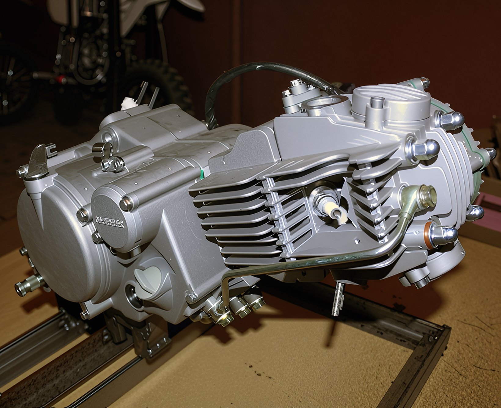
Some operations can be carried out without removing the engine from the motorcycle. These include adjusting the timing gaps, removing the generator and clutch, the cylinder head, and the cylinder itself, replacing the piston, timing chain, and its tensioner. This is convenient since the motorcycle remains on the stand, which must also be removed if the engine is taken out.
Engines for pit bikes sold in Russia are primarily manufactured by the "three Chinese giants" – Lifan (LF), Yinxiang (YX), and Zongshen (ZS). Structurally, they are quite similar, with their main external difference being the shape of the covers on the cylinder head. We will demonstrate the principles of operation using two engines as examples – YX160 (161 cc) and ZS150 (150 cc). For clarity, we will remove the engine from the motorcycle, although some tasks can be performed with the engine in situ.
Engine Disassembly
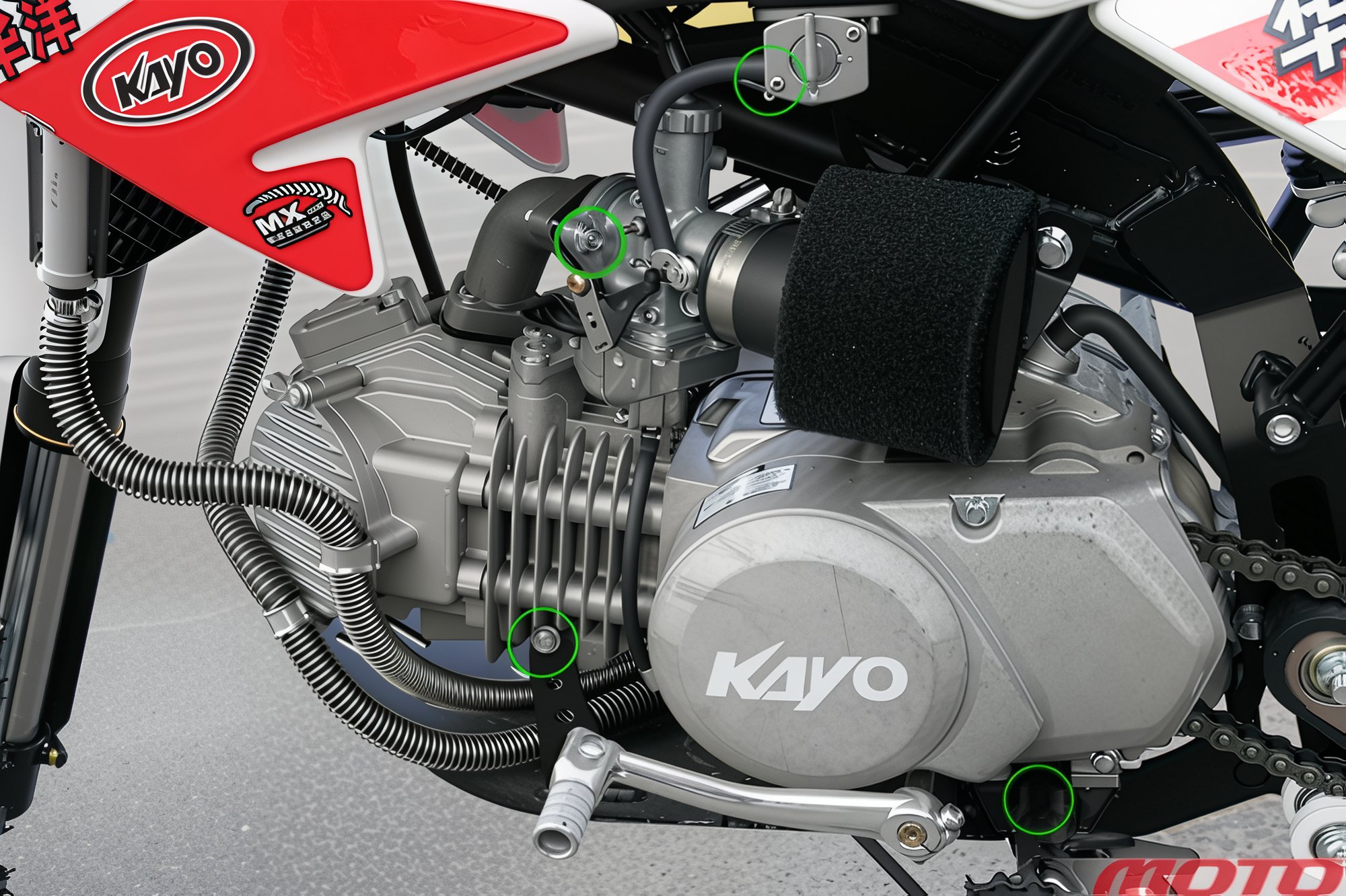
Begin by thoroughly cleaning the engine of dirt (wrap the air filter in a plastic bag during pressure washing). Drain the oil. Disconnect the fuel line (it's easier from the tank; don't lose the wire clamp!). Remove the carburetor with the drain hose by unscrewing two bolts.
By unscrewing its top cover, remove the throttle slide (which remains connected to the throttle cable). Unscrew two bolts at the bottom and two on the sides to remove the engine protection.
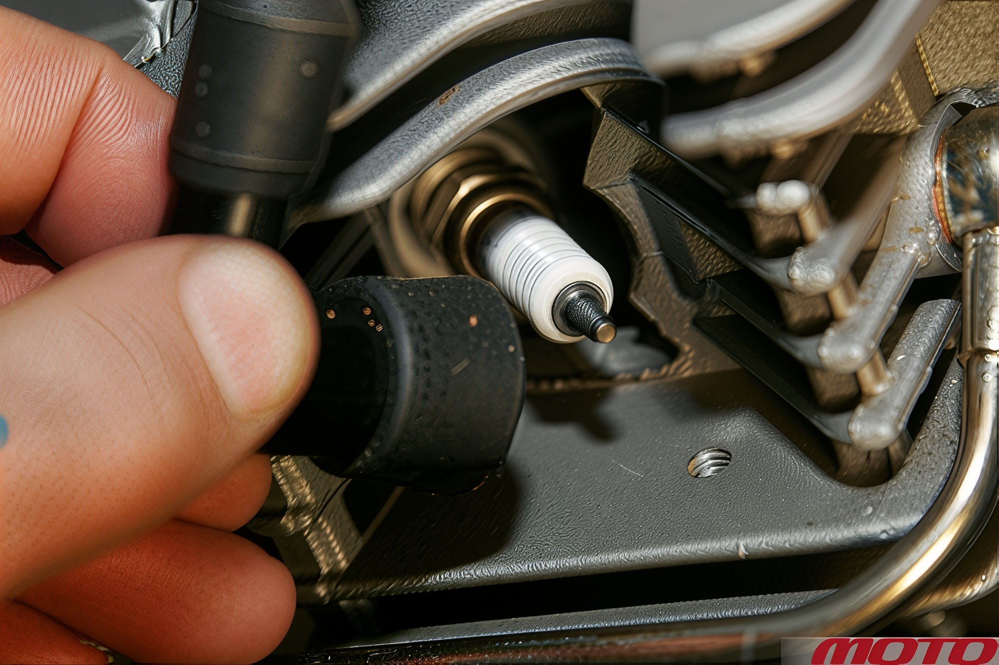
Remove the spark plug cap and unscrew the spark plug (16 mm socket with a rubber insert).
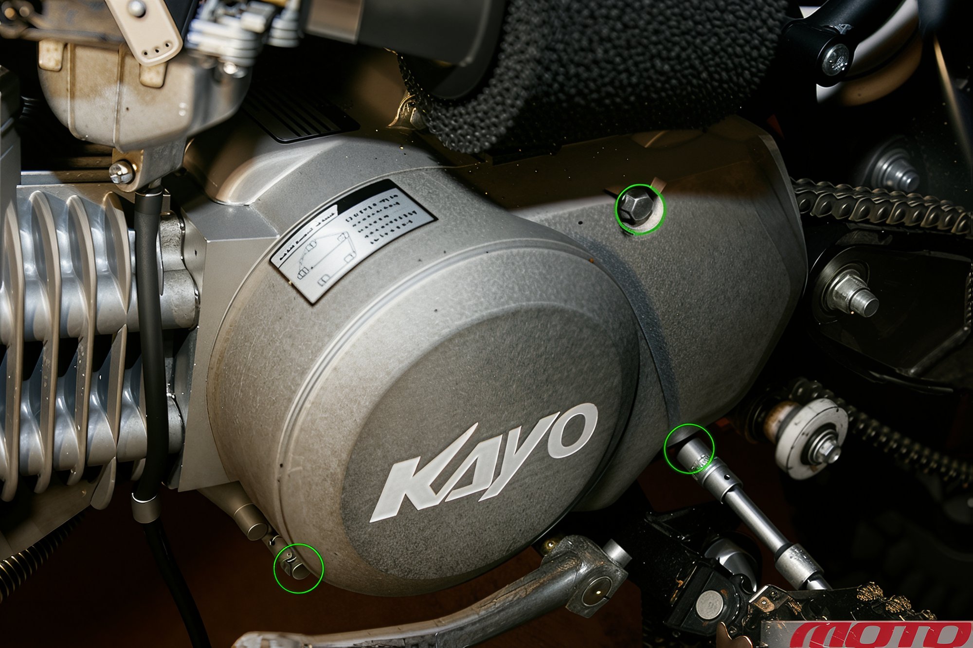
To remove the chain, unscrew three bolts securing the left side engine cover and remove it. Unscrew two bolts securing the drive sprocket, turn the shaped lock washer, remove it, and slide the sprocket off the shaft with the chain. Unscrew the bolt to remove the gear shift lever.
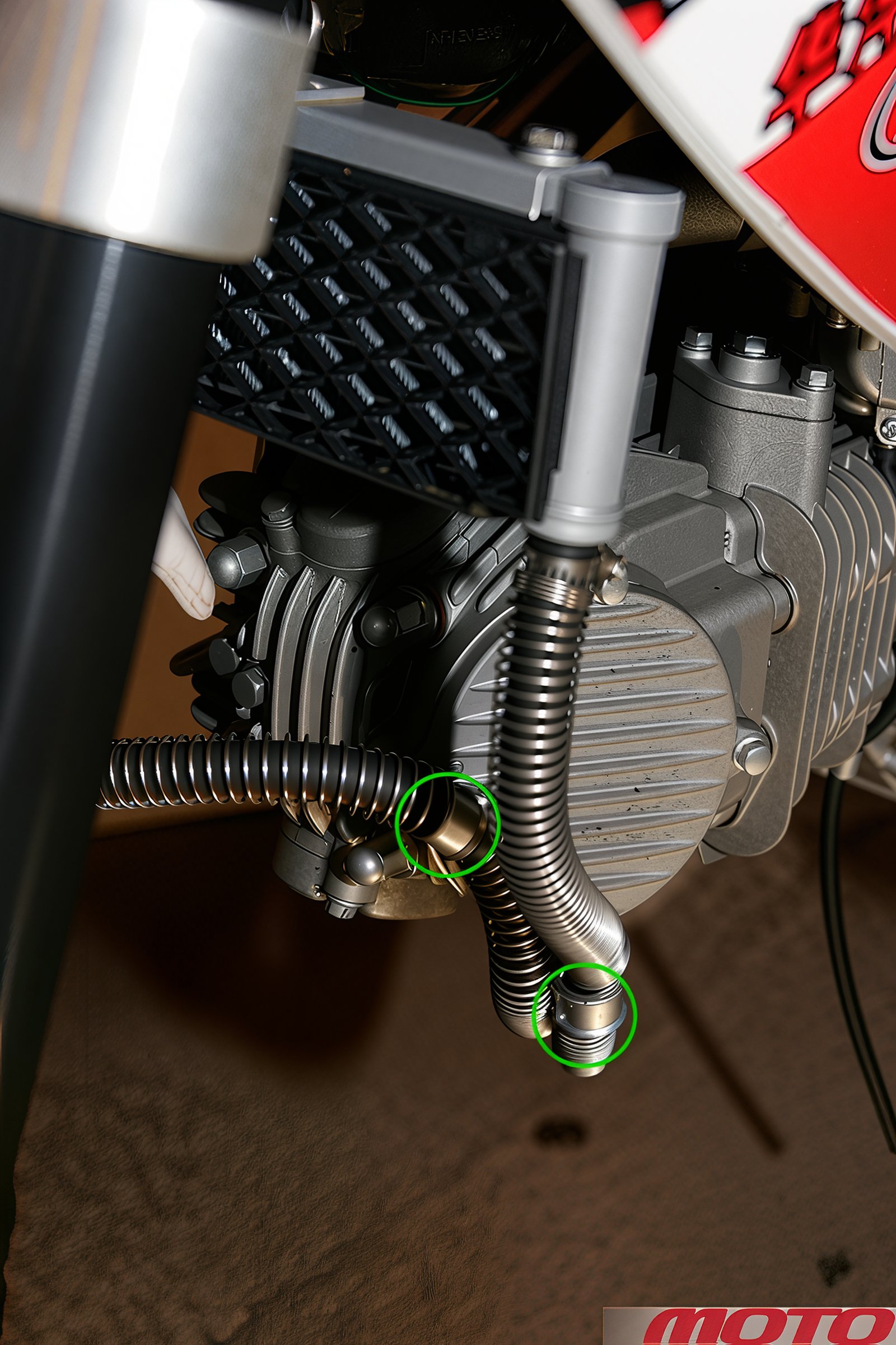
By bending the holders of the oil cooler hoses and loosening the clamps (near the engine), disconnect the hoses (for convenience, the radiator can also be removed).
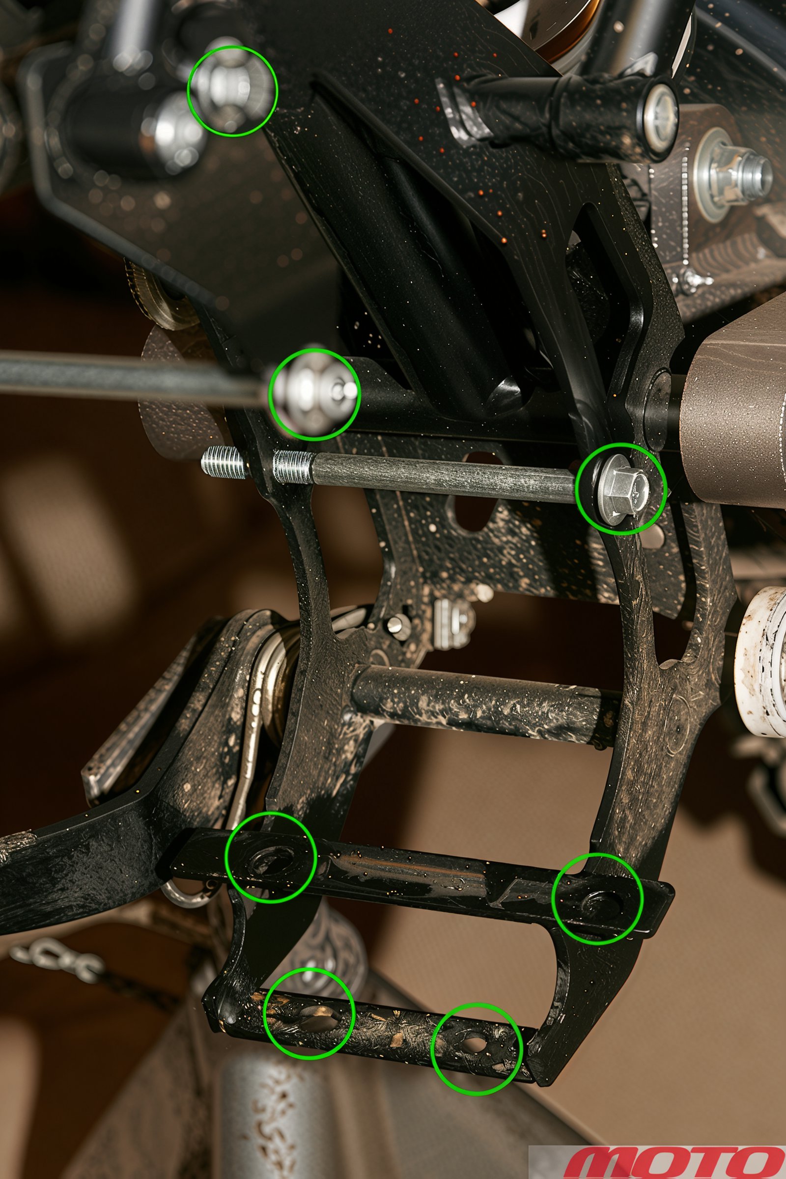
The engine is secured by three transverse bolts (one on top and two at the back) and four underneath – to the stand and frame. For clarity, attachment points are shown on the removed engine. Remember, when the engine is removed with the stand, you must support the frame.
During assembly, a new gasket set will typically be required, as well as copper (or aluminum) washers.
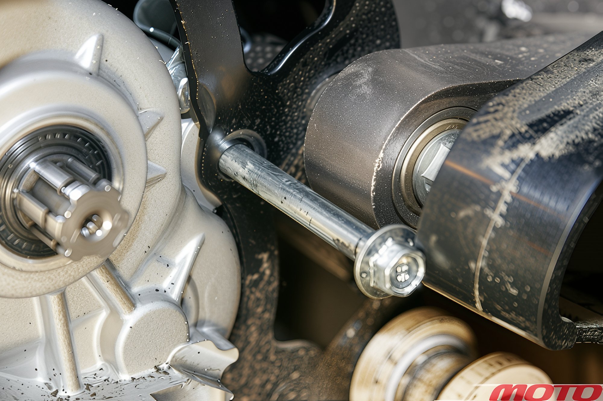
To remove the bottom transverse bolt, on Kayo, you will need to loosen the swingarm rubber pad screws and slide it outward. It is best to remove the engine with assistance. It's easier for one person if the bike is laid on its side.
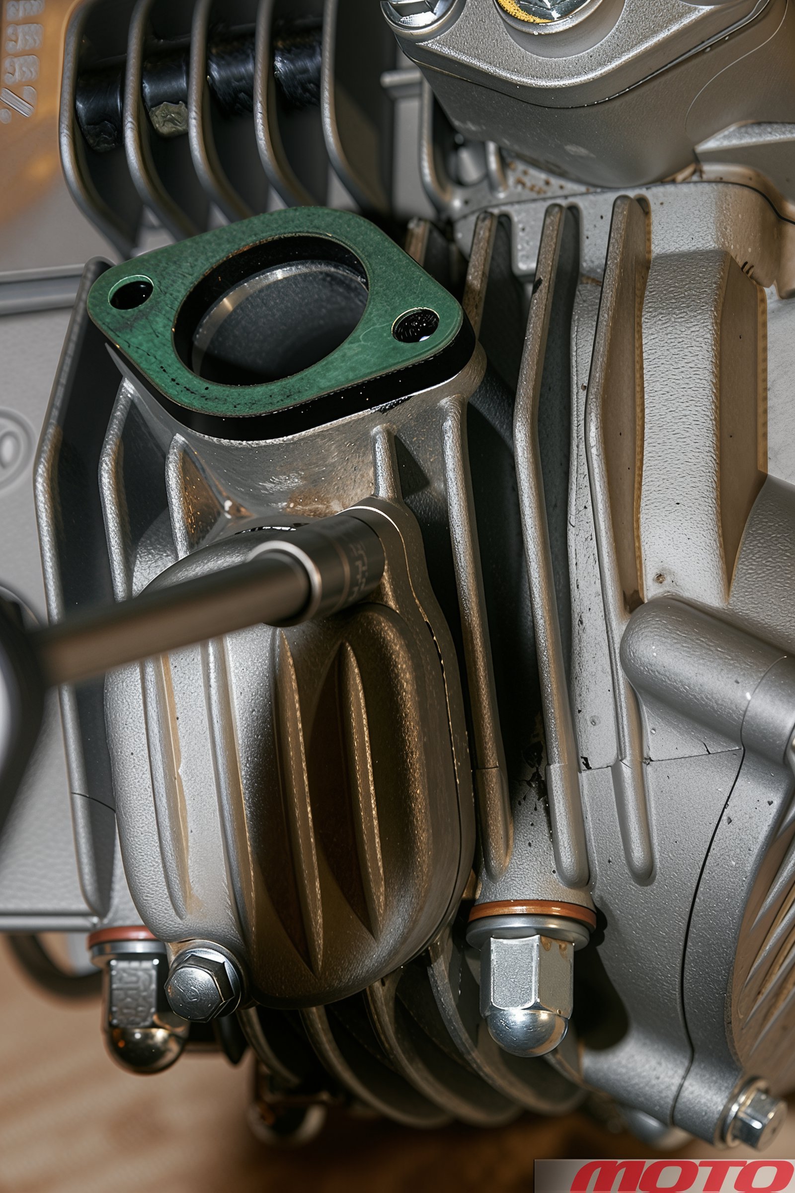
Unscrew the carburetor pipe bolts and remove the pipe. Unscrew the cover bolts for valve access.
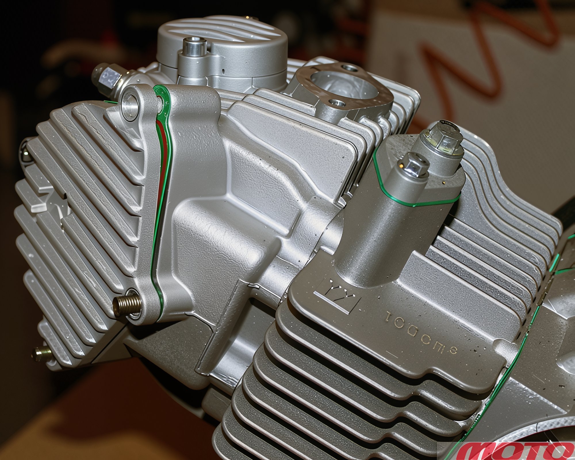
Check and note the timing marks' positions. To do this, unscrew the four nuts (YX) or bolts (ZS) holding the camshaft gear cover and gently remove the cover with the gasket (cardboard or rubber).
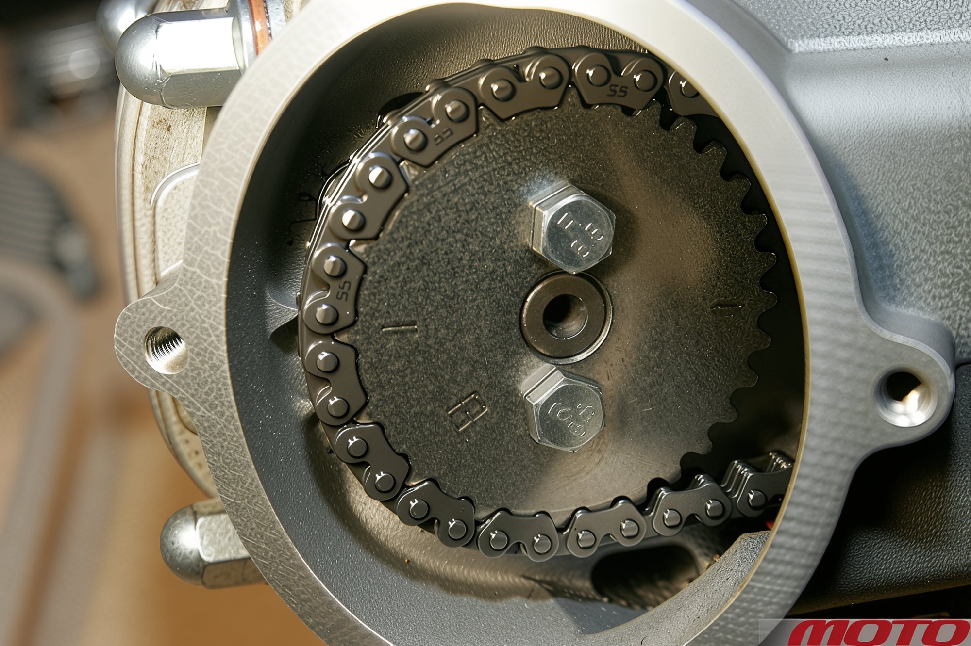
Align the marks on the gear with the lug on the head. The FL marking (Front Left) is, as expected, at the front left, meaning in the position where both valves are closed (the position for checking and adjusting clearance).
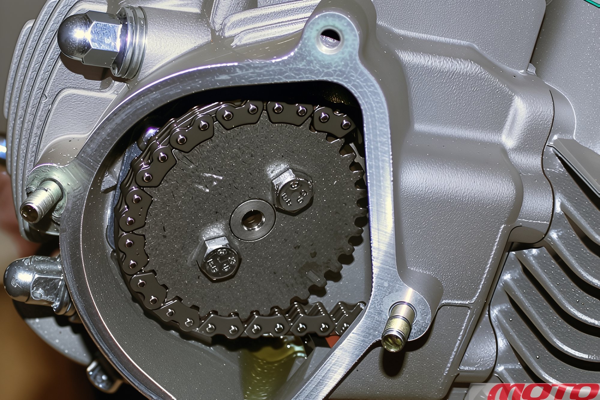
There may be other marks (letters, a diamond, etc.). If the mark doesn't reach the lug, rotate the shaft using the flywheel (generator rotor). When installing, ensure the gear is oriented correctly (its holes are symmetric and allow different positions).
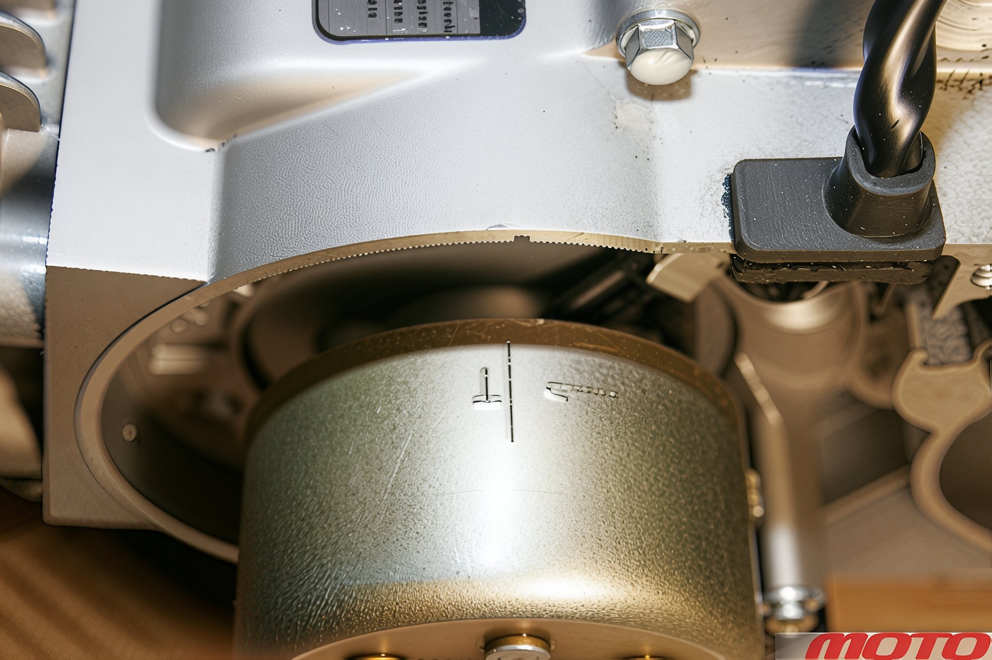
The "T" mark on the flywheel should be opposite the notch in the upper part of the left crankcase half.
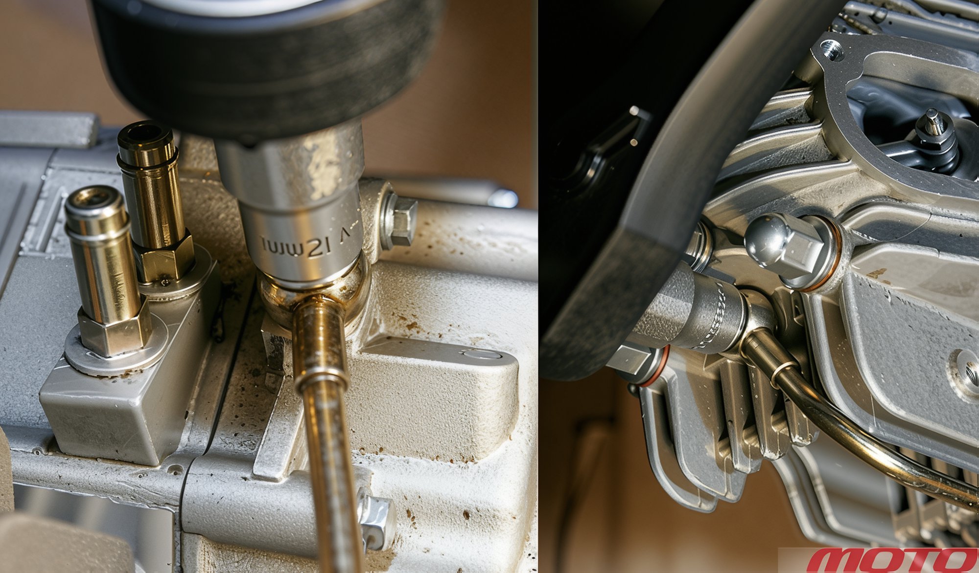
Unscrew the oil line fittings and remove them.
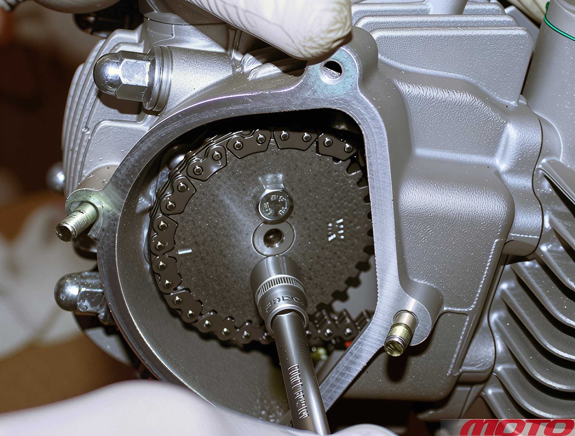
Unscrew two bolts securing the camshaft gear.
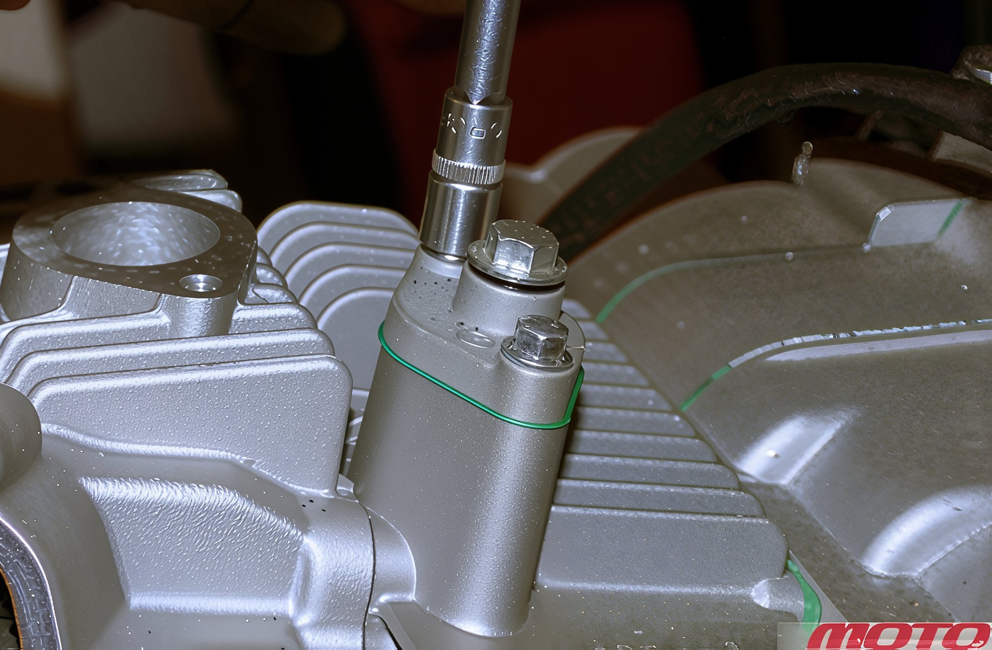
Unscrew two bolts securing the chain tensioner and remove it (its rod should extend completely).
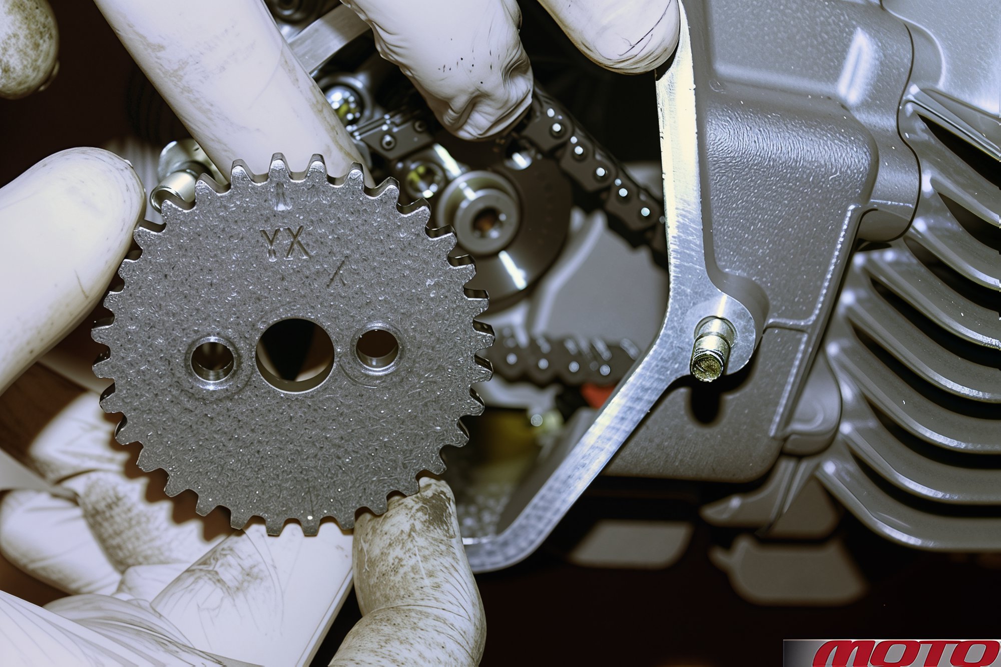
Remove the gear while holding the chain. If the engine does not need to be completely disassembled, secure the chain with wire.
It is more convenient to reassemble the engine with two people, but in principle it can be done alone, although the engine will need to be secured on a stand (it can be easily made from steel profiles), preferably rotatable. A full engine overhaul (rarely required) would take 4-5 hours.
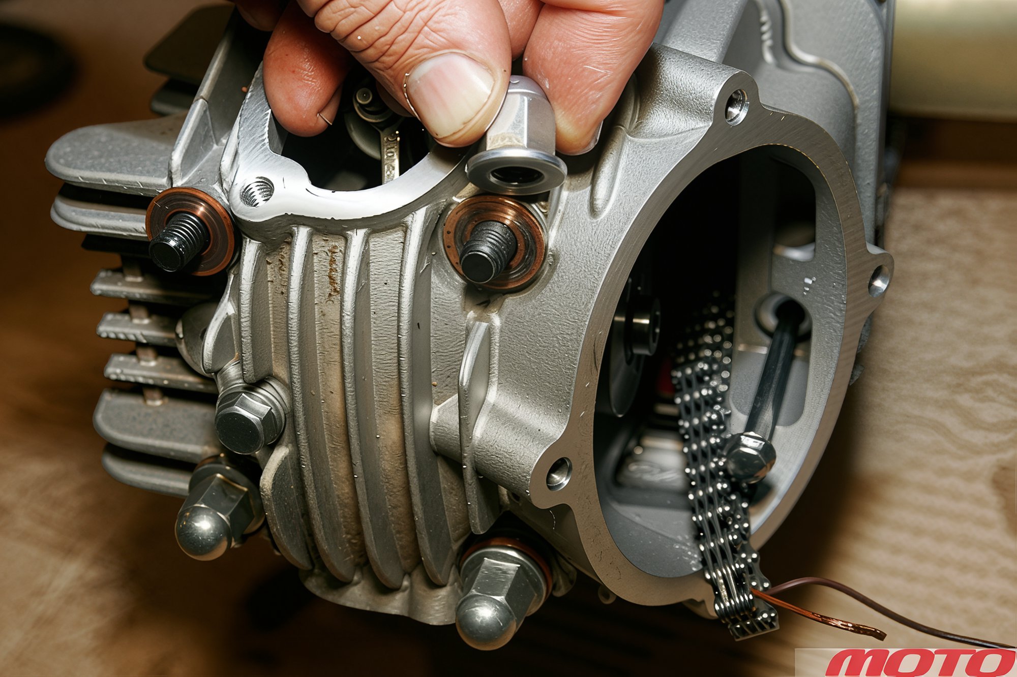
Unscrew four cap nuts and two bolts (under the removed timing cover) securing the cylinder head.
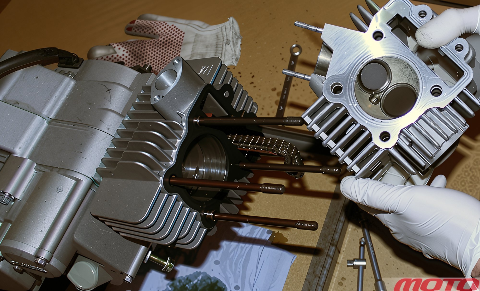
Remove the cylinder head. Its disassembly is shown below. Remove the metal gasket remaining on the cylinder.
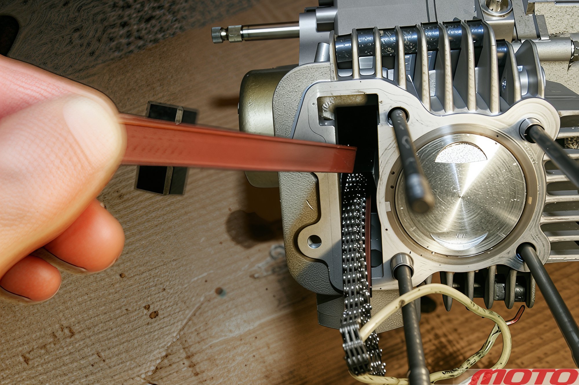
Remove the chain guide...
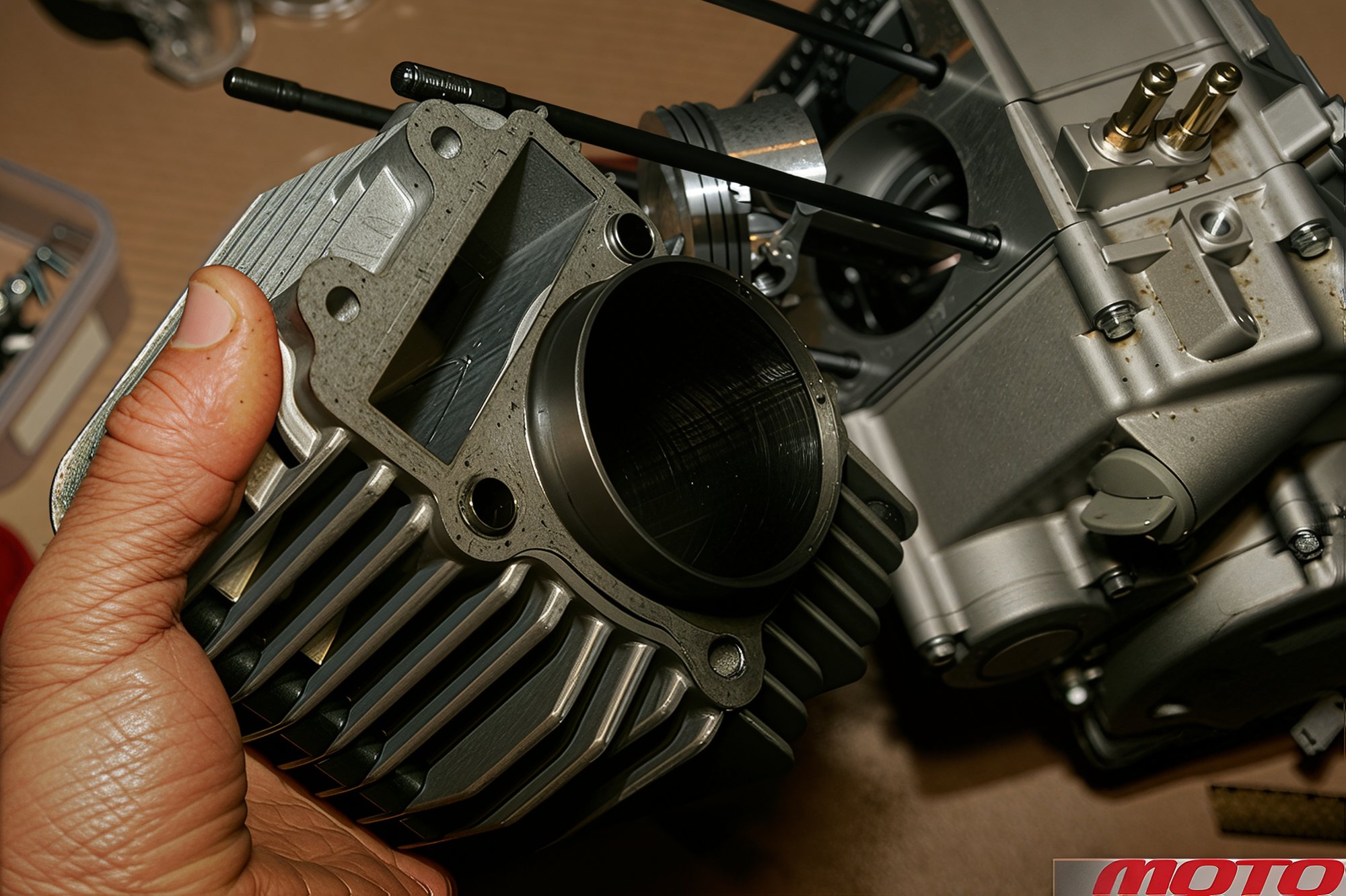
...and remove the cylinder. If necessary, first gently separate its gasket to avoid damaging it.
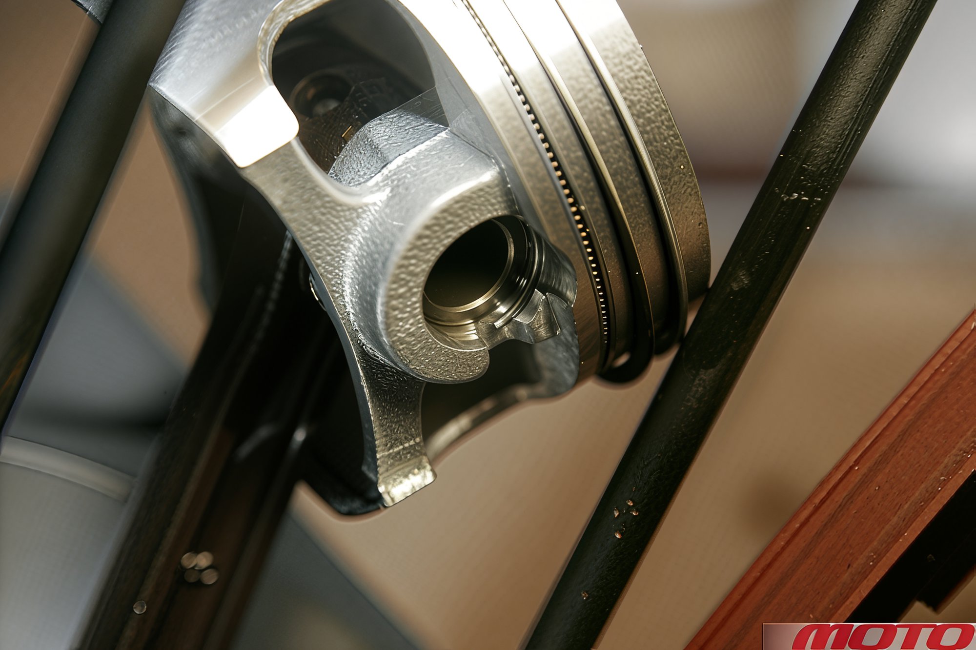
To remove the piston, pry and remove the retaining ring with thin pliers, then extract the gudgeon pin (through and through).
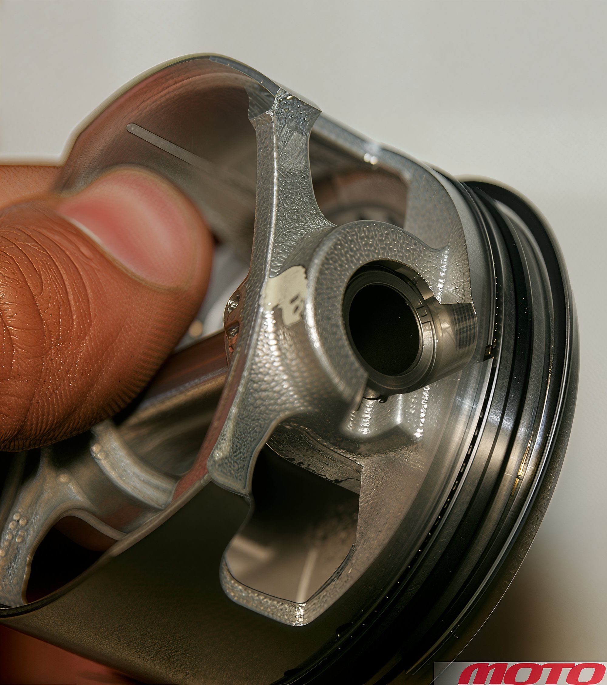
The piston, pin, and connecting rod are matched by clearances. When replacing parts, pay attention to the color codes.
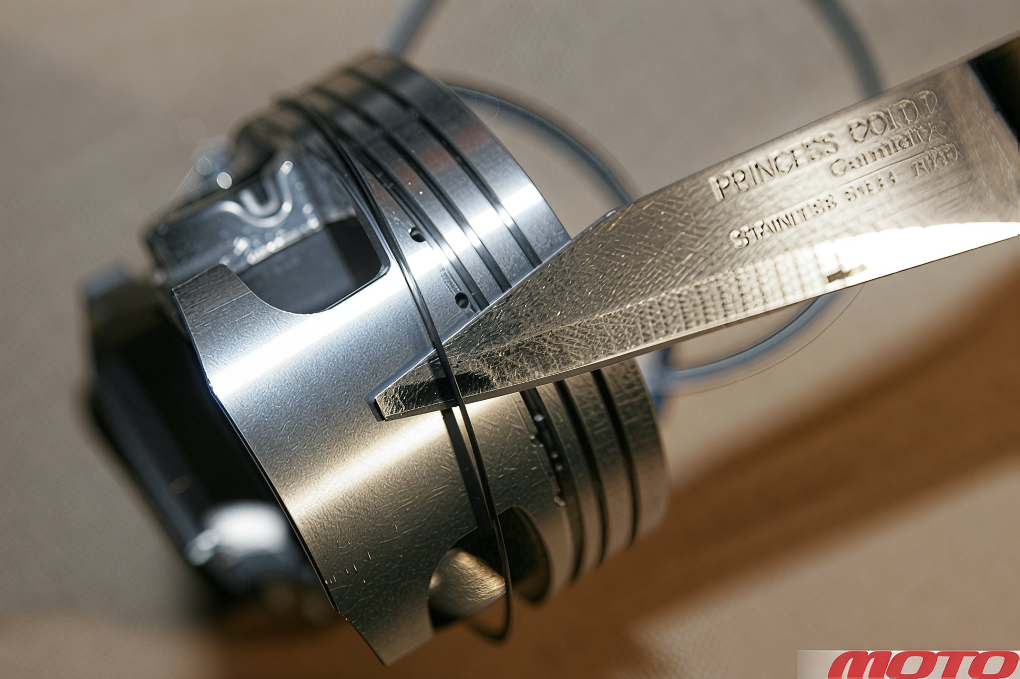
Remove the rings, gently spreading the ends with fingers. To avoid scratching the cylinder during removal/installation, it's best to move them along surfaces of brass, plastic (from a bottle), or, in extreme cases, a thin knife can be used.
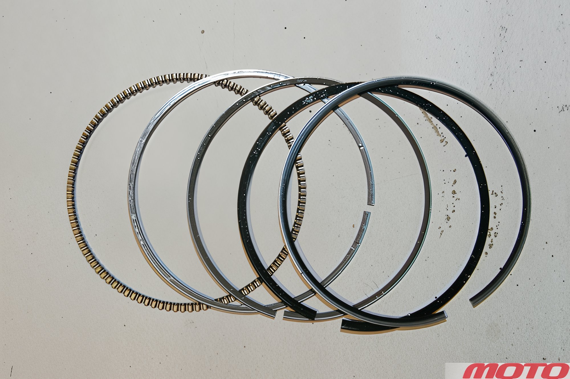
The removed rings. The oil scraper consists of two thin rings and a spring spreader. It's installed first during assembly because the "spring" has protrusions that press against the thin rings, preventing it from protruding beyond their diameter.
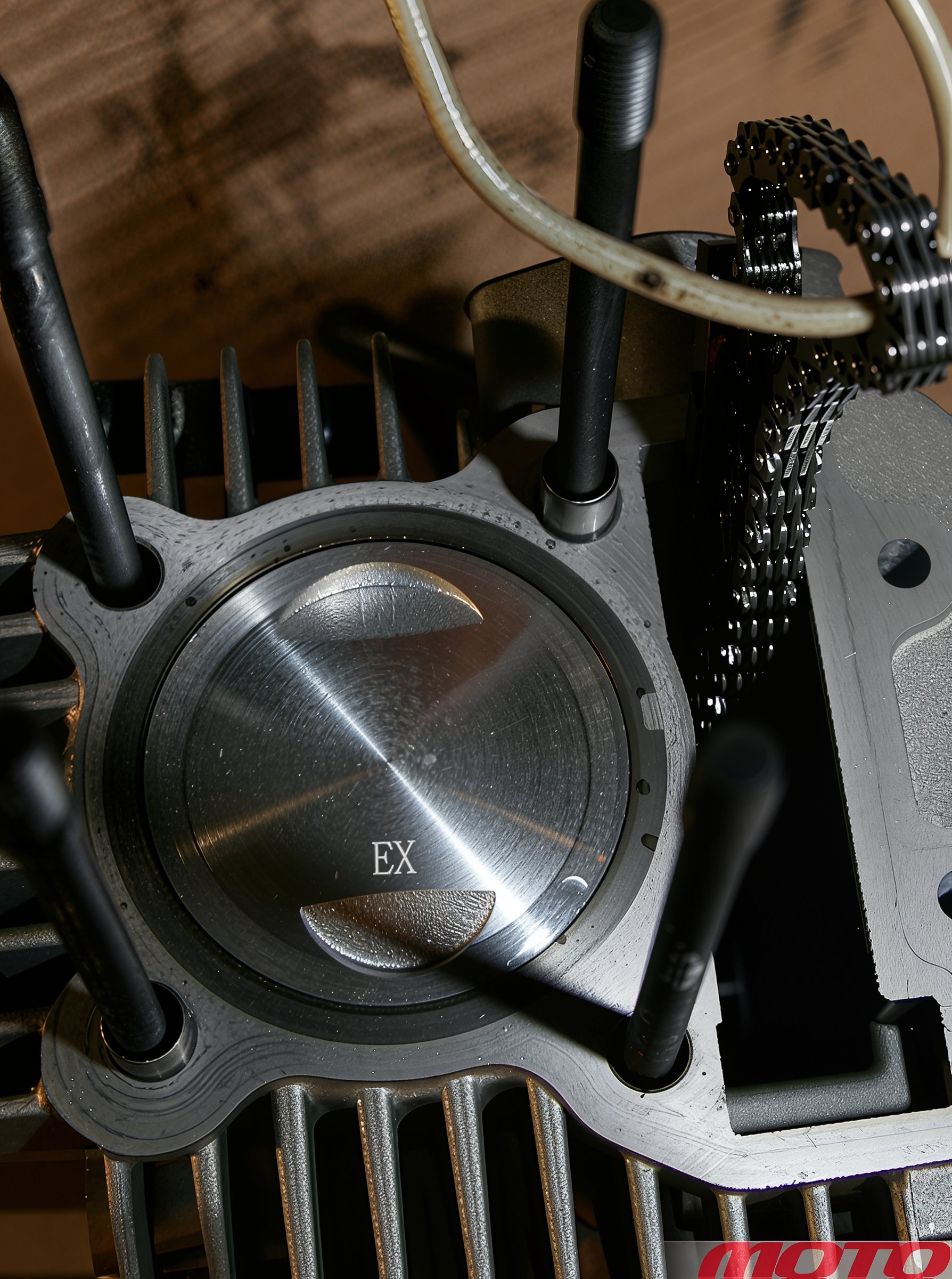
When assembling, pay attention to the piston orientation. The large valve cutout (IN mark) should face the intake (faces up), and the small one (EX) should face the exhaust (faces down).
Full disassembly requires special tools. However, we will show what can replace most tools without harm. The only thing worth acquiring is a rotor puller (flywheel), paying attention to the rotor's thread direction - both right and left-hand threads can be found.
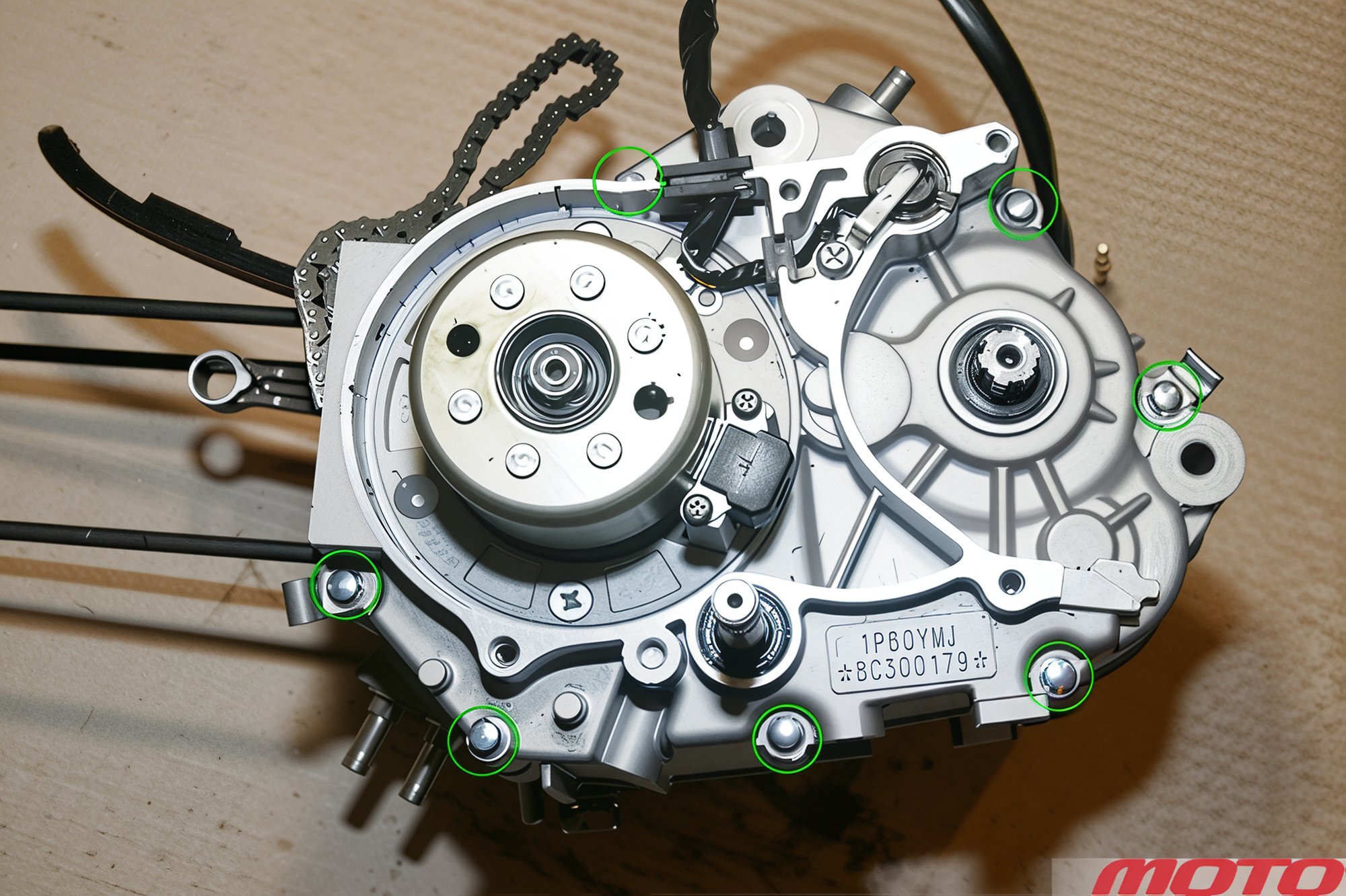
If disassembling the engine without a stand, it is more convenient to first unscrew the bolts pulling the crankcase halves together.
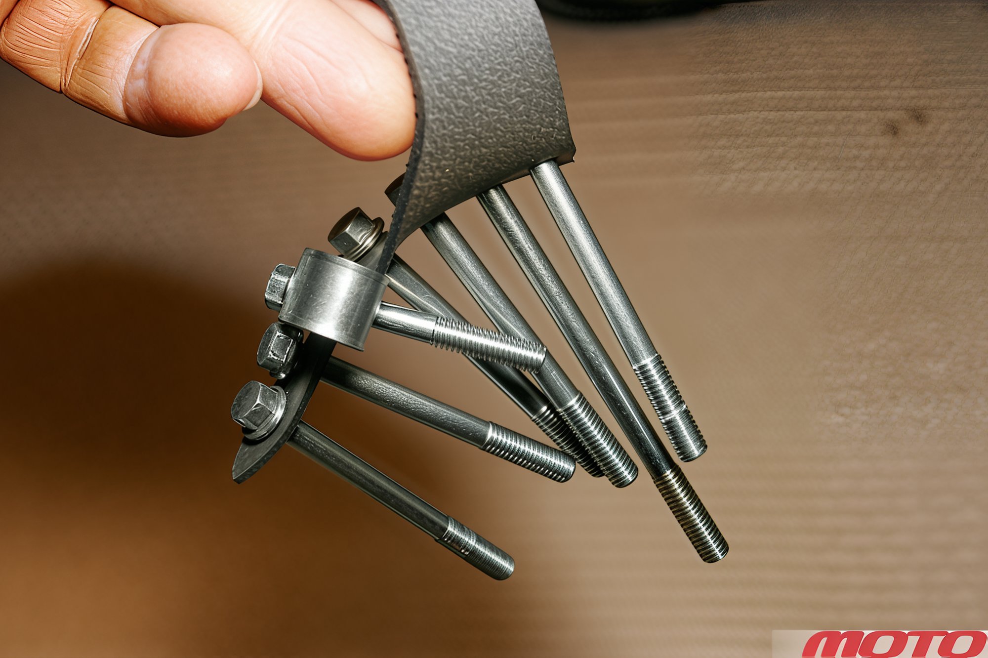
To avoid confusion, use a rubber strap with holes.
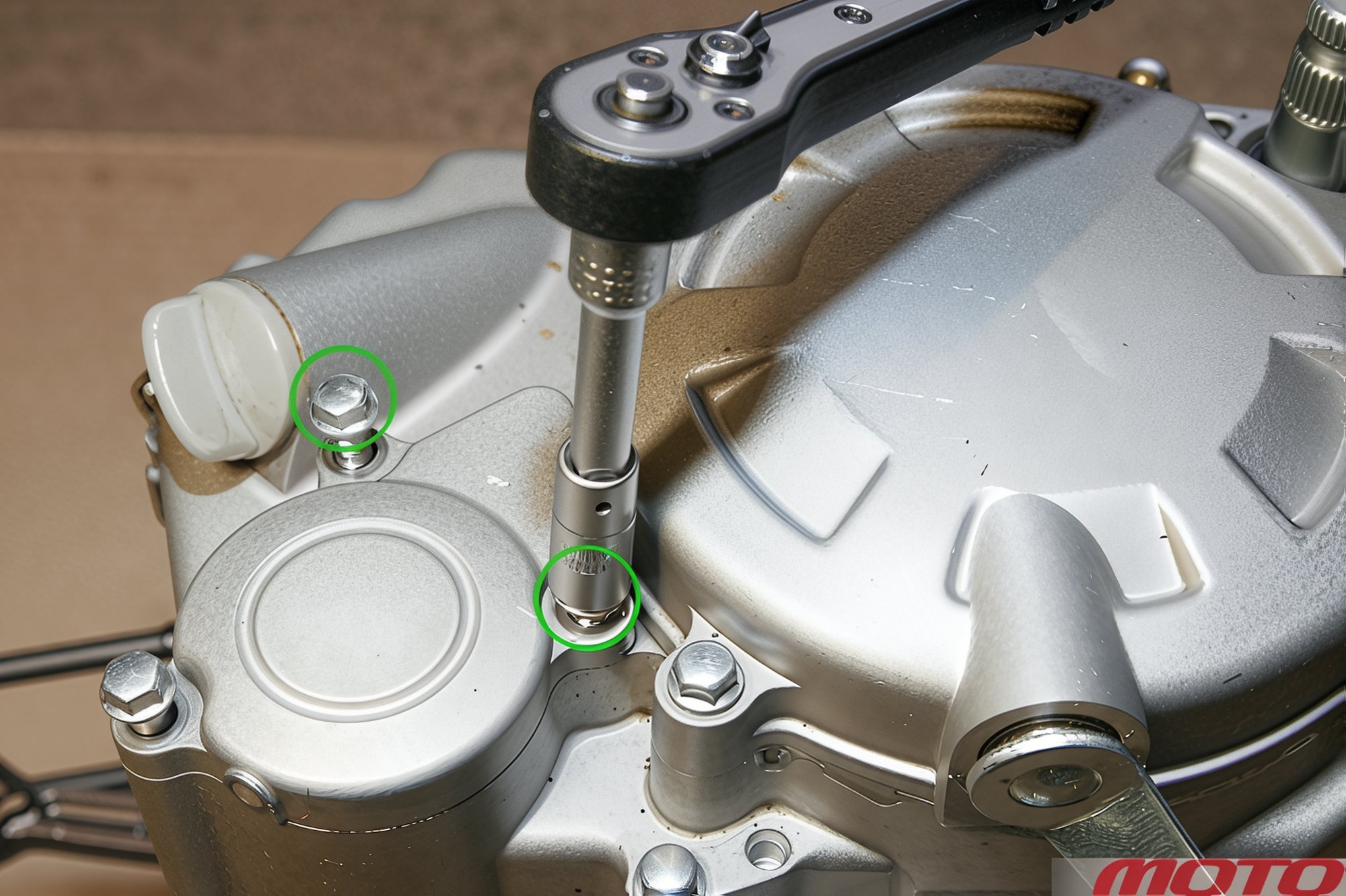
Unscrew the bolts securing the right cover (the two circled bolts only undo if the oil filter needs removing)...
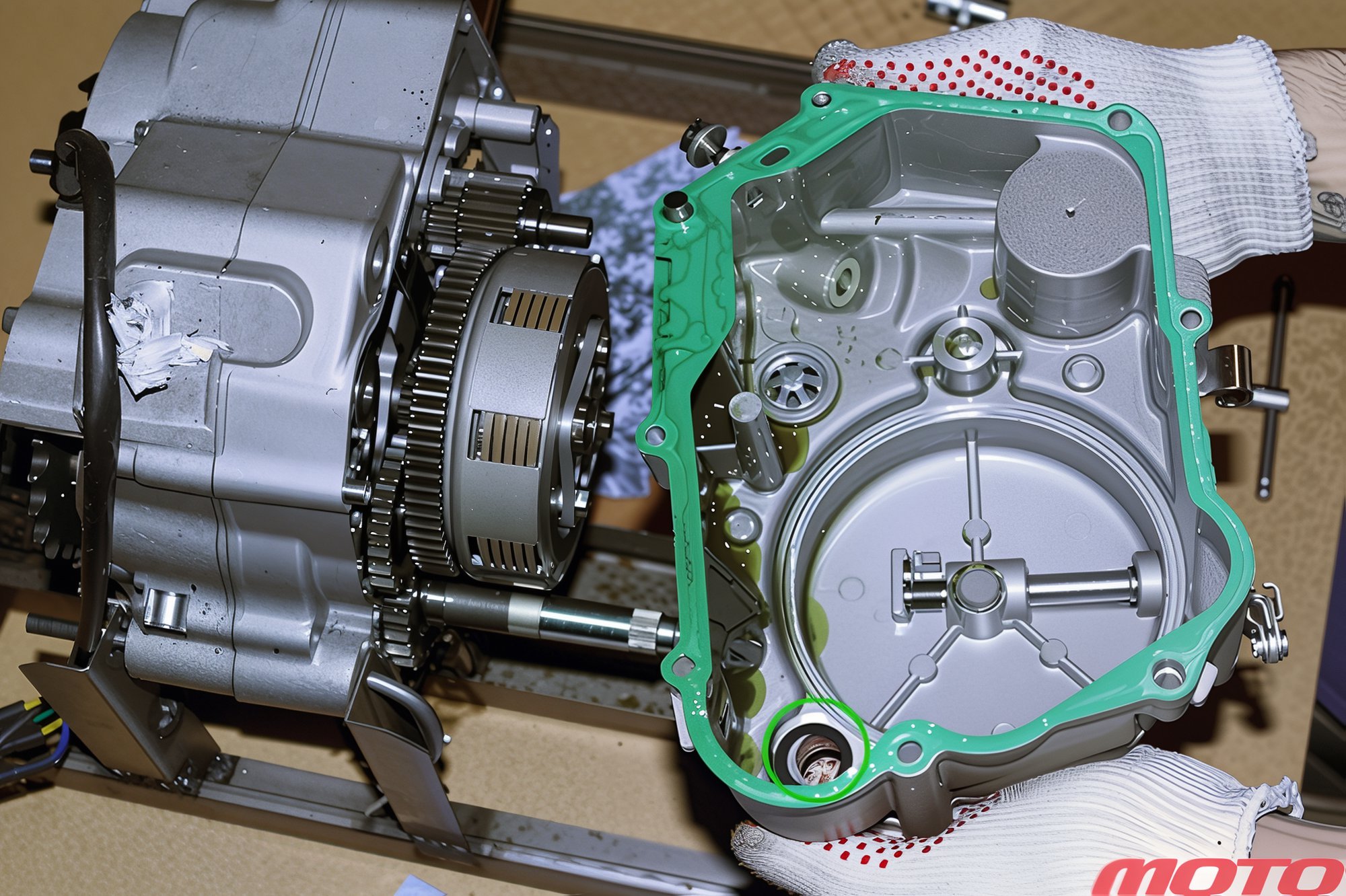
...and remove it. Don't lose the kickstarter shaft washer!
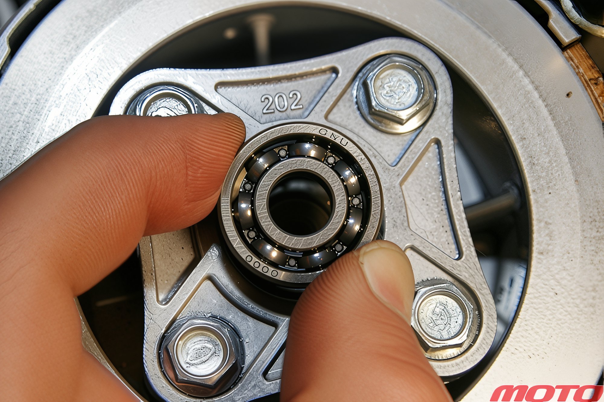
Remove the clutch release bearing and, after unscrewing four bolts...
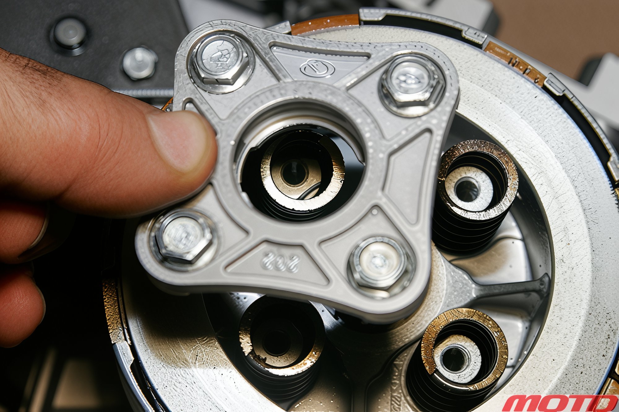
...remove the pressure plate and remove four springs.
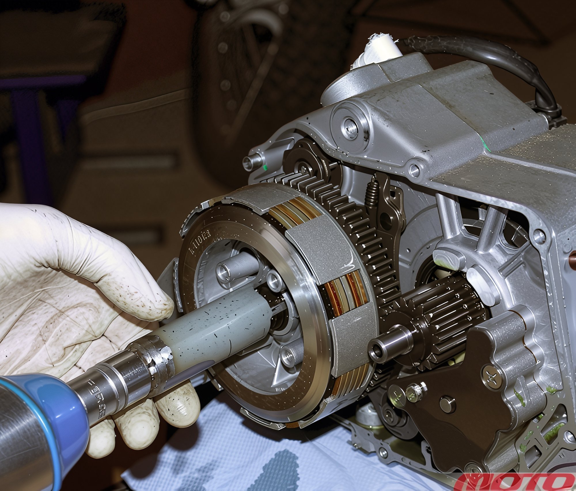
Unbend the lock tabs on the clutch basket nut, use a special tool and pneumatic impact wrench to unscrew it.
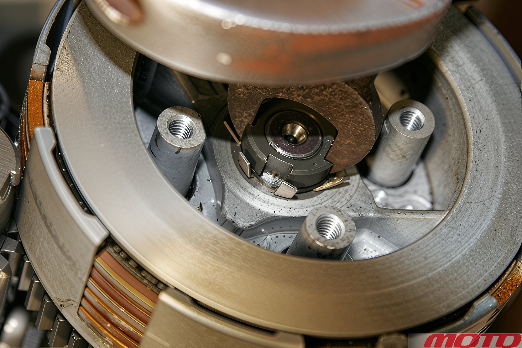
In the absence of such tool, use a 17 mm open-end wrench with narrow jaws, clamped by a large adjustable wrench. (In extreme cases, carefully use a chisel and hammer - "My Pit Bike" note)
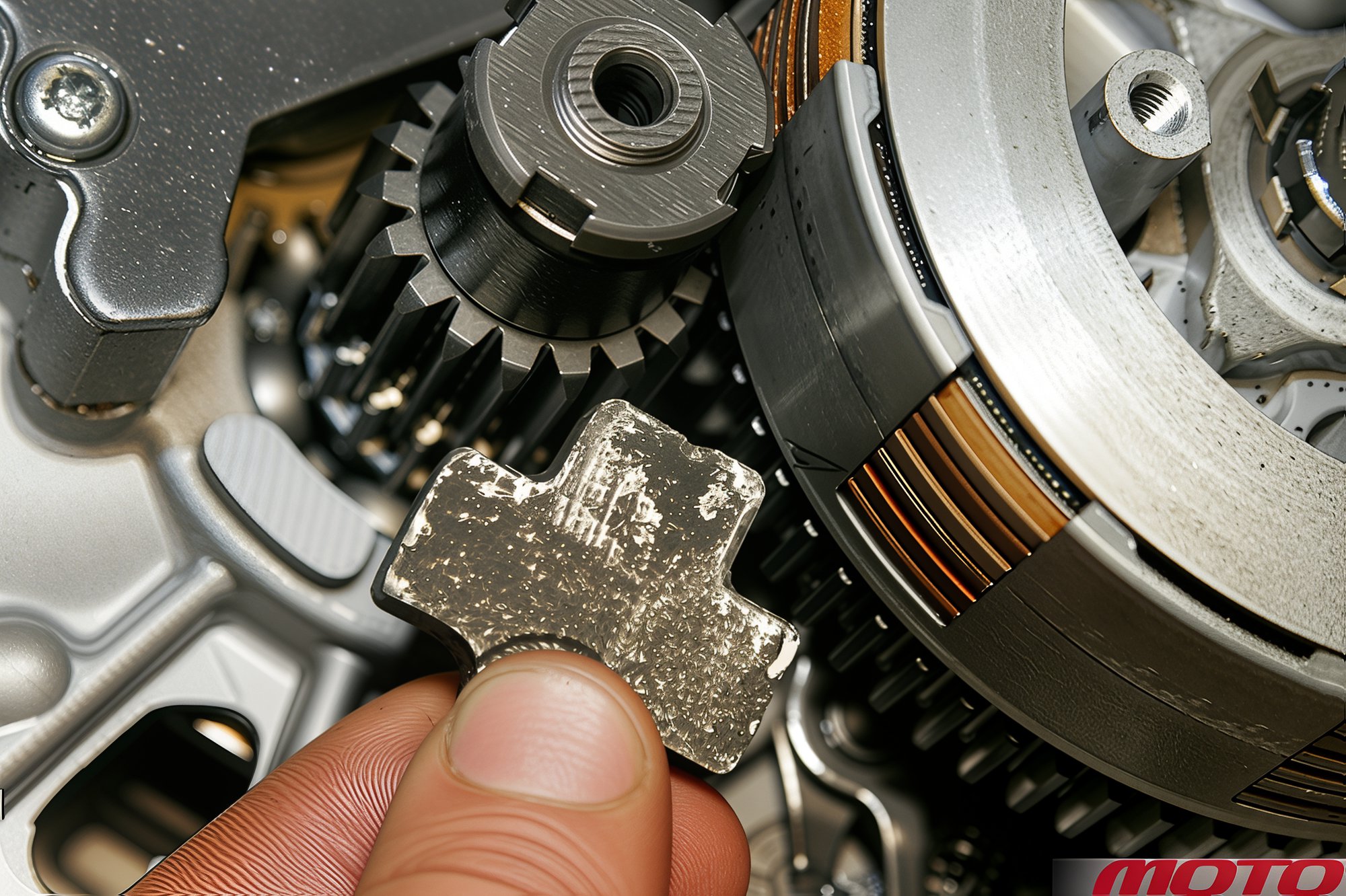
The shafts can be conveniently fixed with a universal aluminum gear stopper to prevent rotation (an inexpensive "Zhiguli" brake system tee).
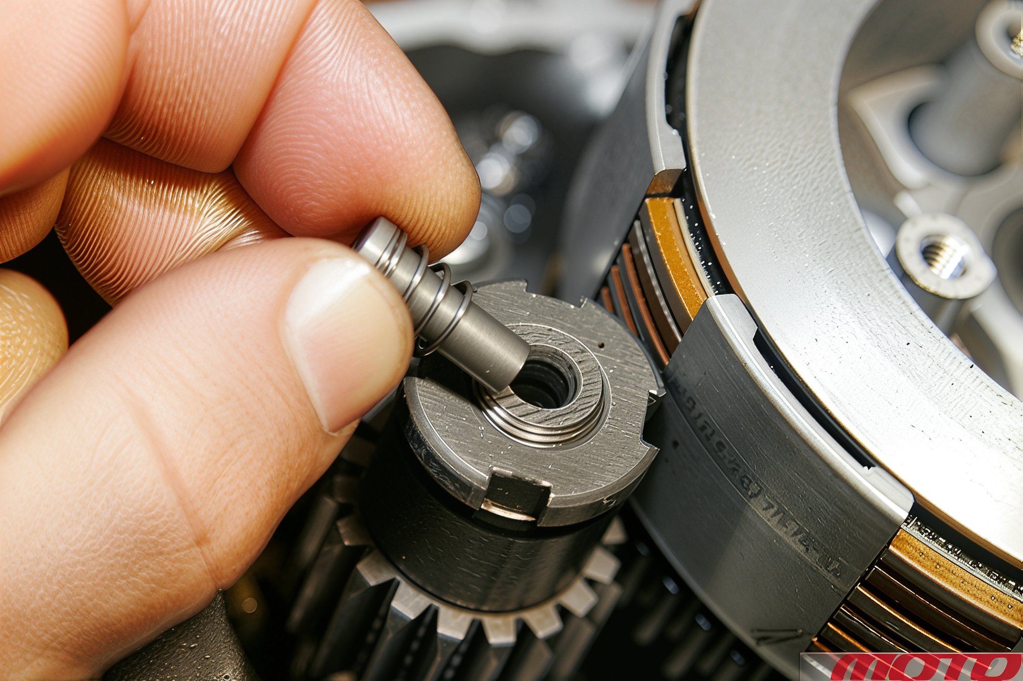
Remove the oil system part from the crankshaft bore (ZS150, not found in YX160).
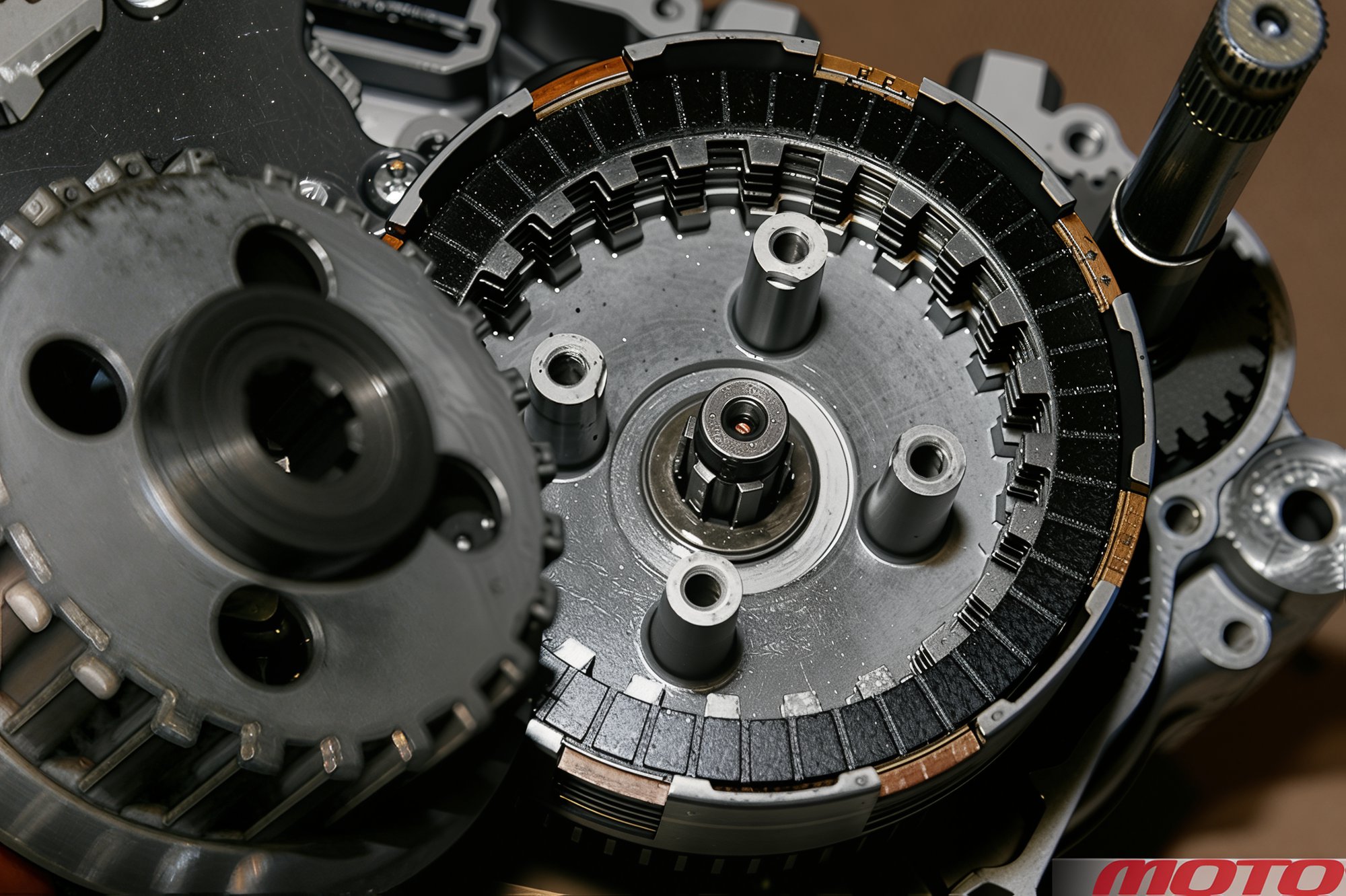
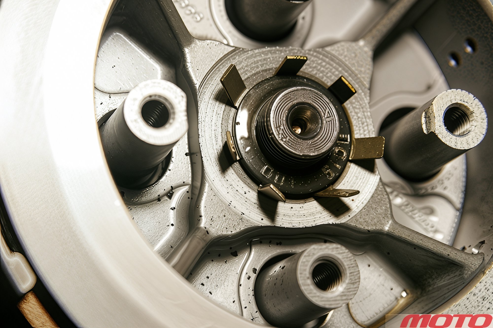
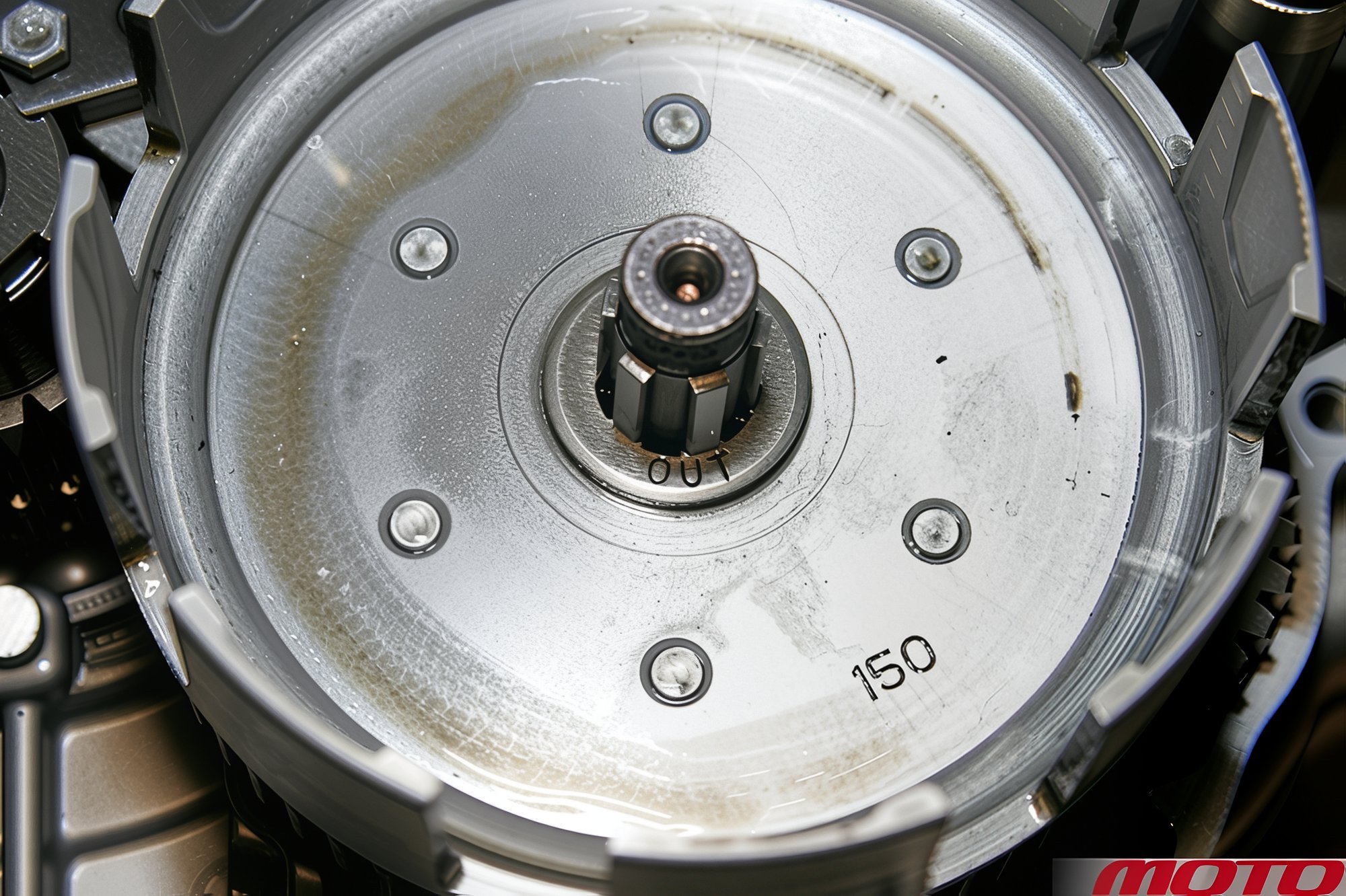
Remove the drum, discs, and clutch basket, paying attention to the washer positions (out side - facing outward).
It is advisable to place fasteners into individual, tightly closing (!) jars according to the units being disassembled. Rubber rings easily cut from automotive or motorcycle tubes will help secure screws in covers or washers and gears on shafts.
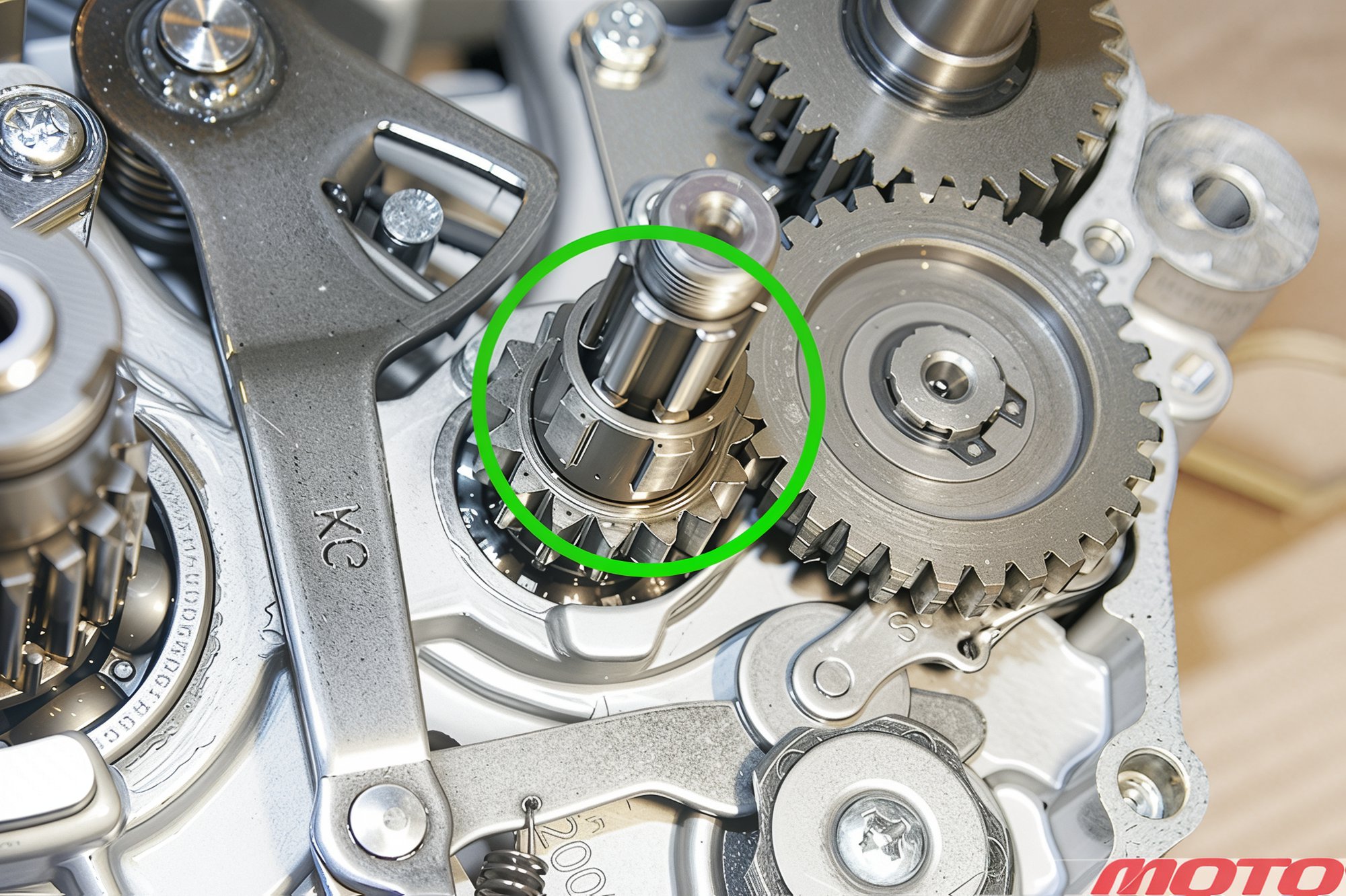
Remove the clutch basket sleeve.
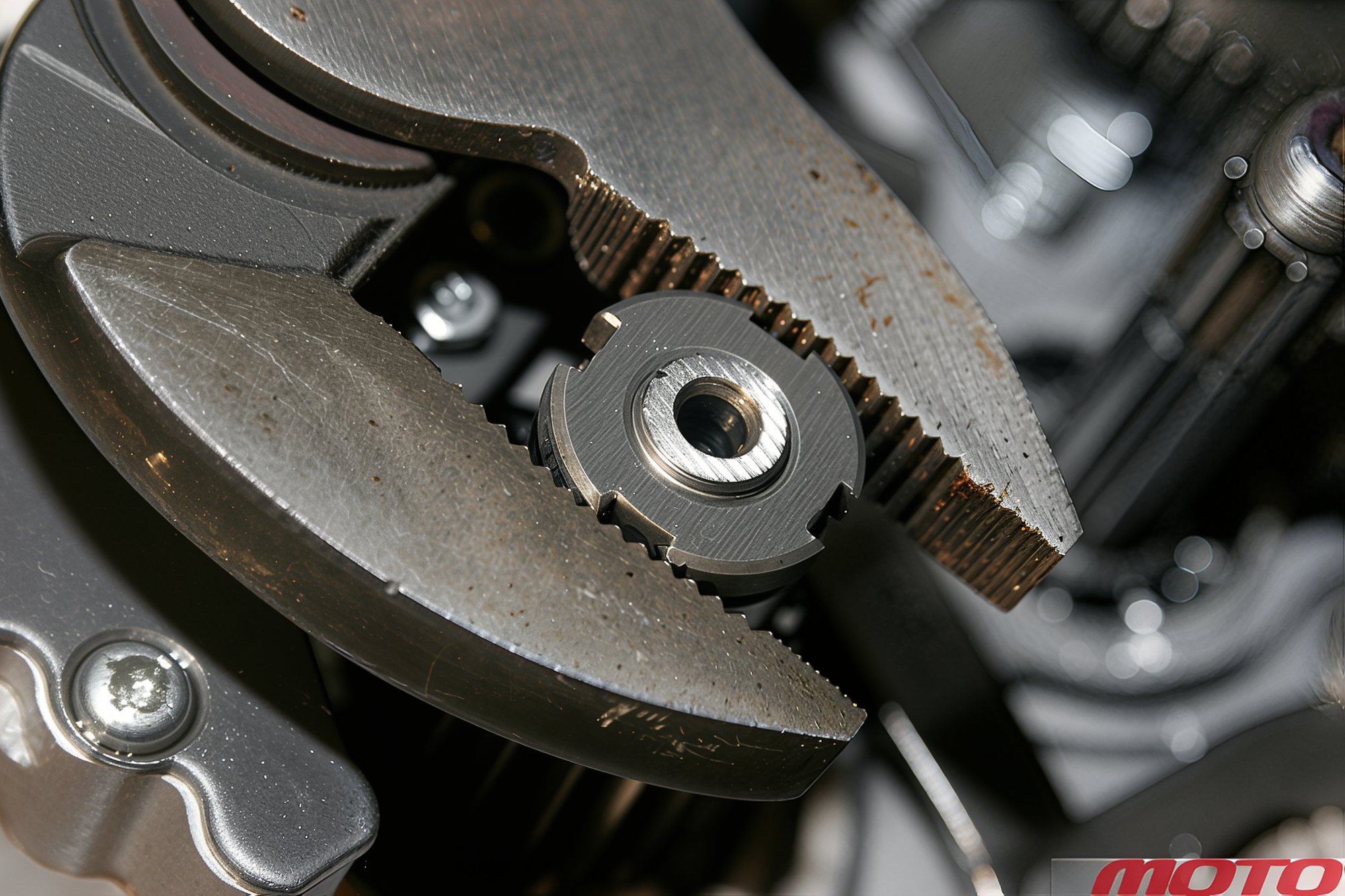
The crankshaft nut can be unscrewed with large pliers. Under it is a conical washer (outer side labeled - out side). Fix the shaft by the generator rotor (see below).
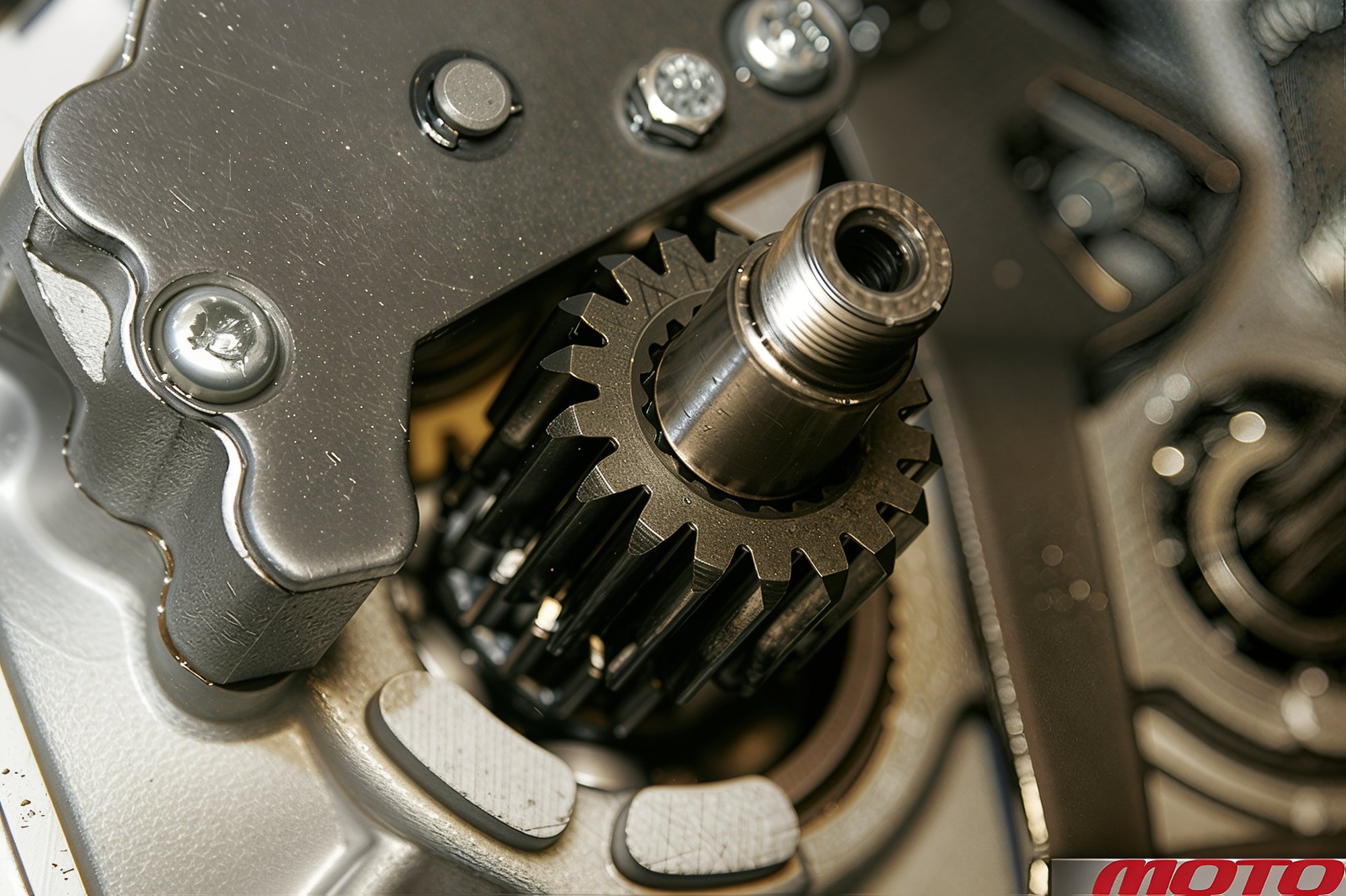
Remove the drive gear of the motor transmission from the shaft and the oil pump drive (underneath).
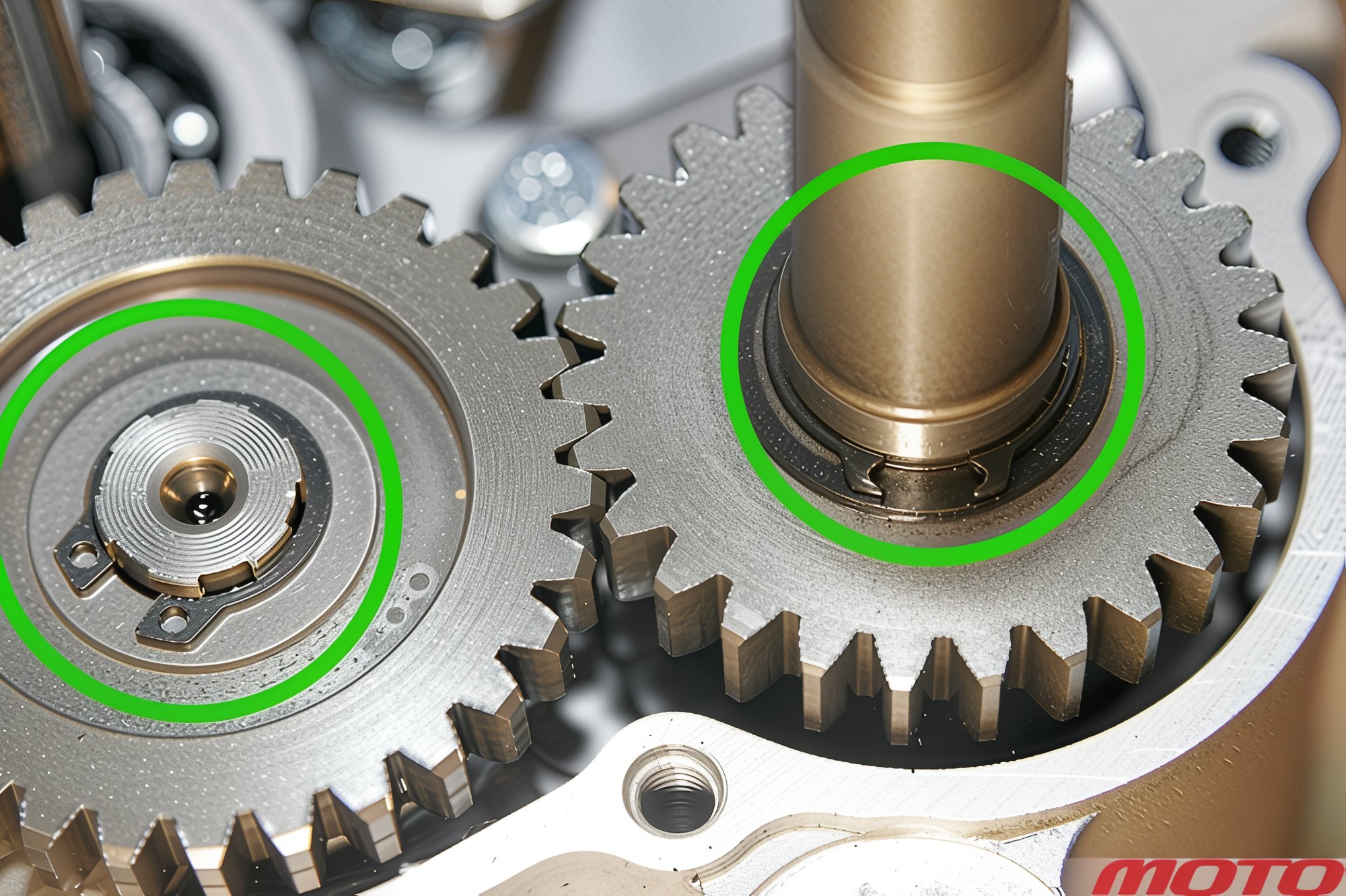
Remove the circlips from the idler gear (on the transmission shaft) and kickstarter gear, and then remove the gears with washers.
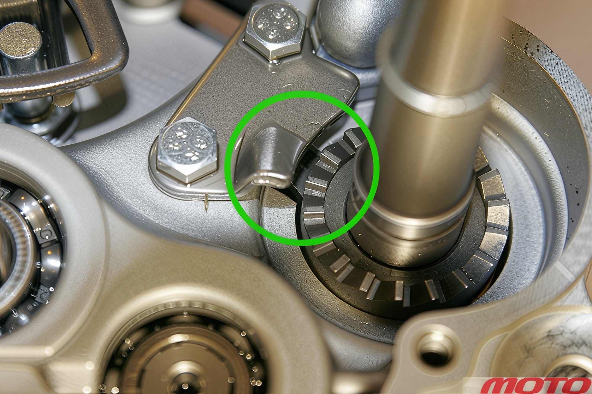
Lightly tap the crankcase halves apart with a rubber mallet. Then, slightly rotate the kickstarter shaft, passing the pawl stop through the casting slot...
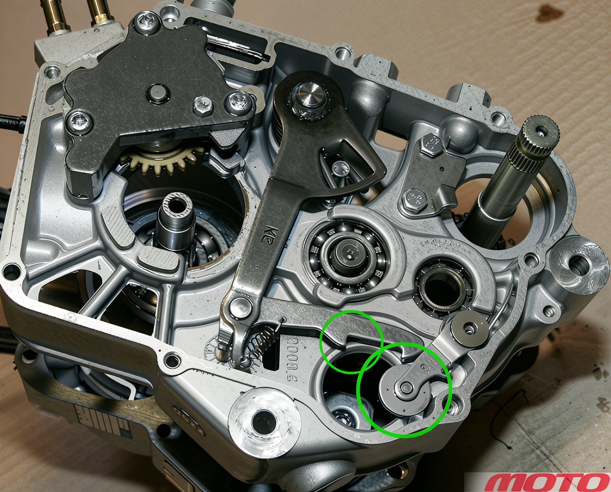
...and, using fingers, move the shifting and detent lever off the copying shaft, then remove the right crankcase half.
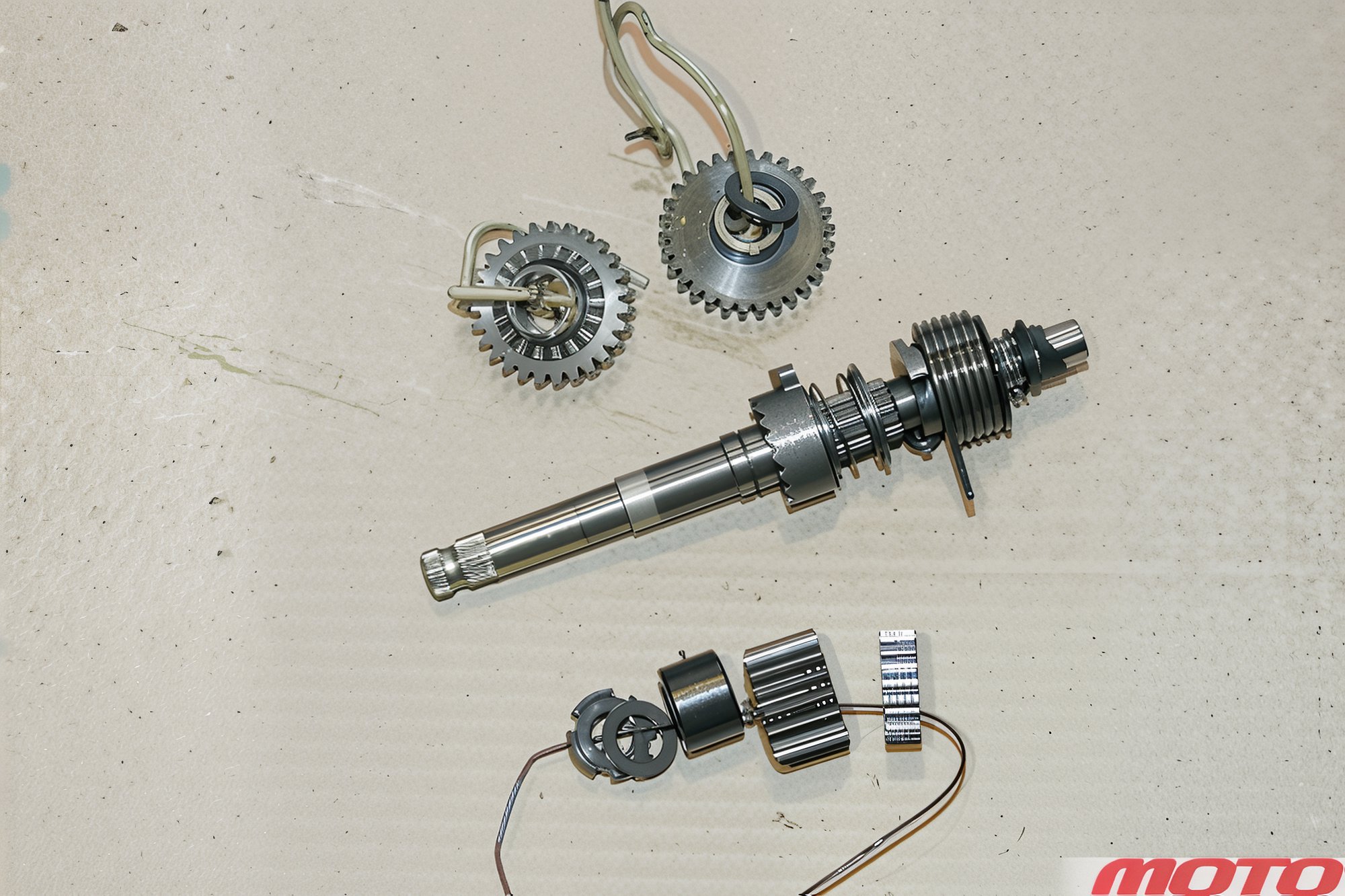
Gears, washers, and circlips have been removed. To prevent the washer on the shaft end from being lost, secure it with a rubber ring.
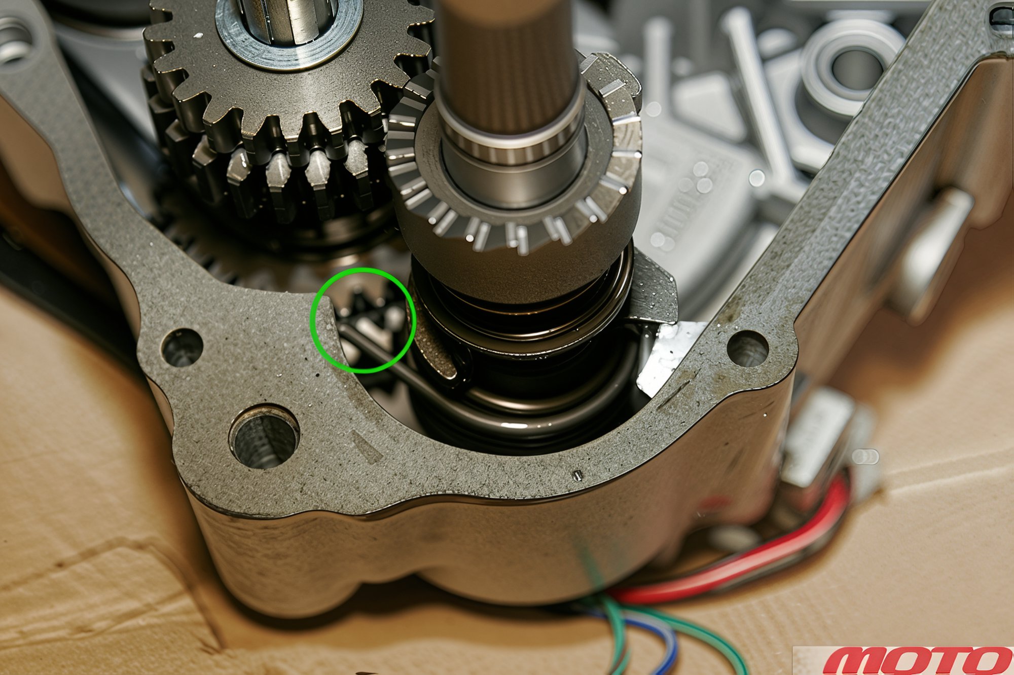
Disengage the spring lug, remove the kickstarter shaft.
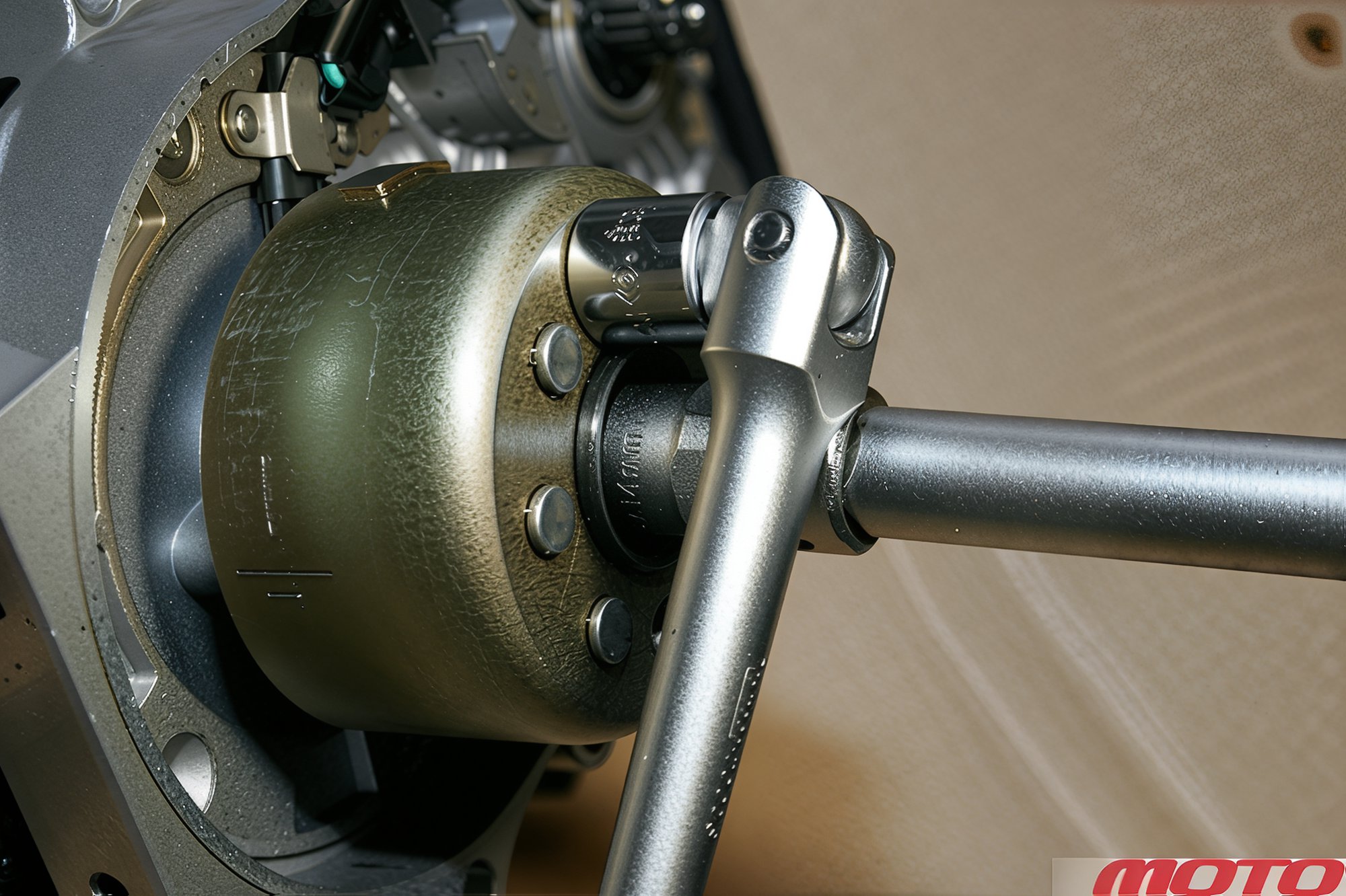
If there is no rotor holder, secure it by inserting a key or suitable bolt into the window, to unscrew the nut. Do the same during tightening (as shown in the photo). Be cautious, a long bolt may damage the stator! Alternatively, the nut can be unscrewed easily using a pneumatic or electric tool.
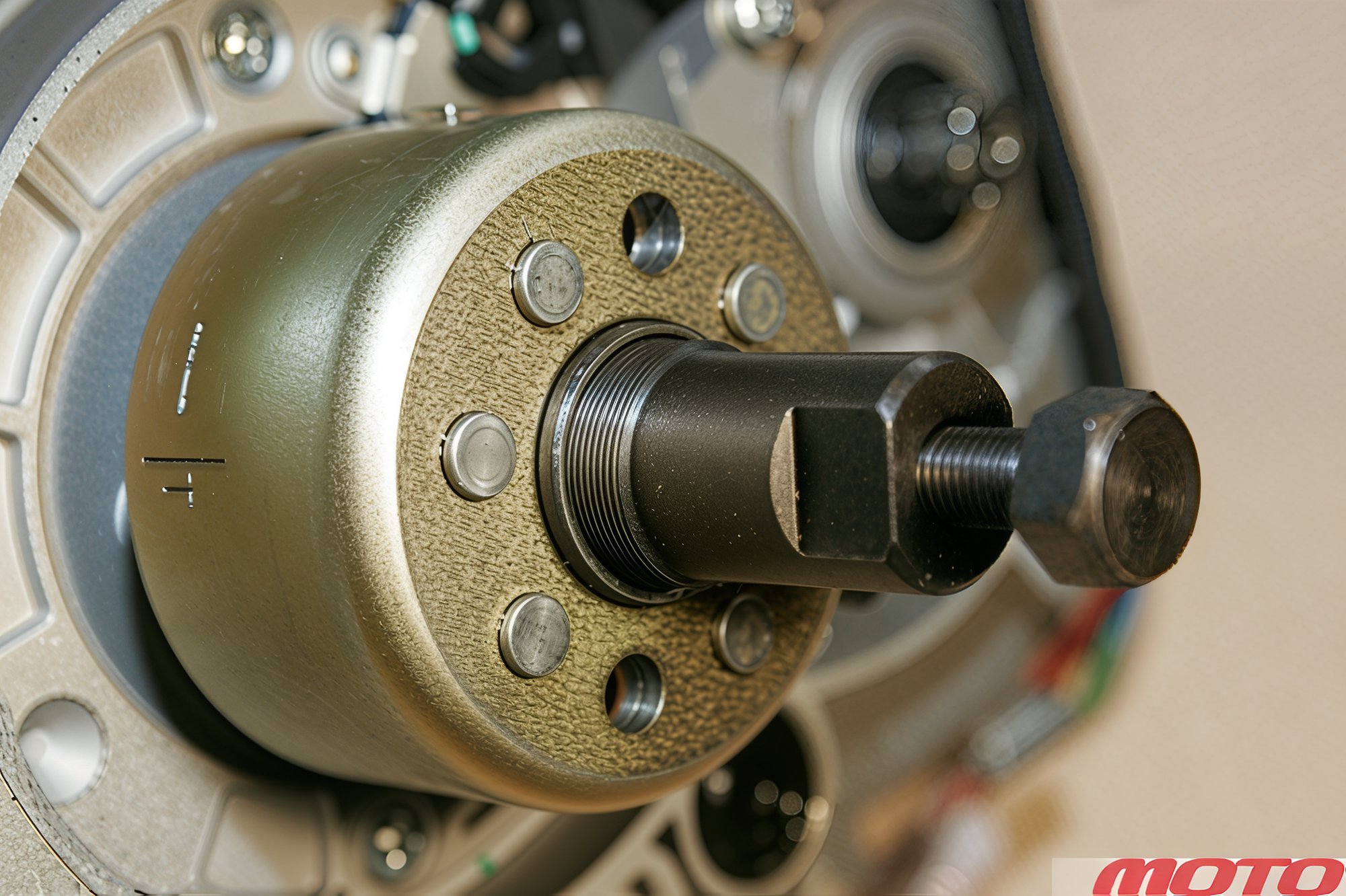
To remove the rotor, a central bolt puller is needed. Note: our engines typically have a left-hand thread for it, though there are variants.
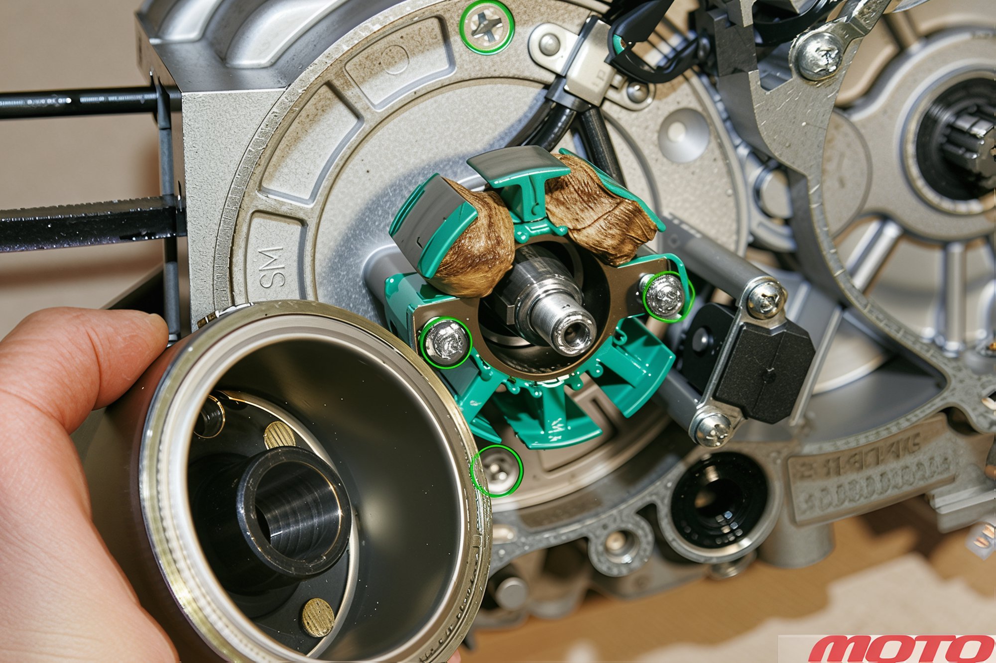
The stator is secured by two screws, as is its base.
Align the timing marks when assembling the engine, first position the camshaft so both valves are closed, and do not shift it until the chain is precisely engaged on both cogs, with the piston at TDC (as indicated by the flywheel mark). Verify TDC position by a screwdriver through the spark plug hole, gently turning the crankshaft by the flywheel.
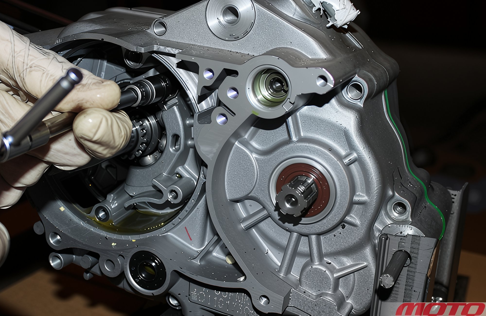
If it is necessary to extract the chain tensioner strip, you will need to remove the stator base.
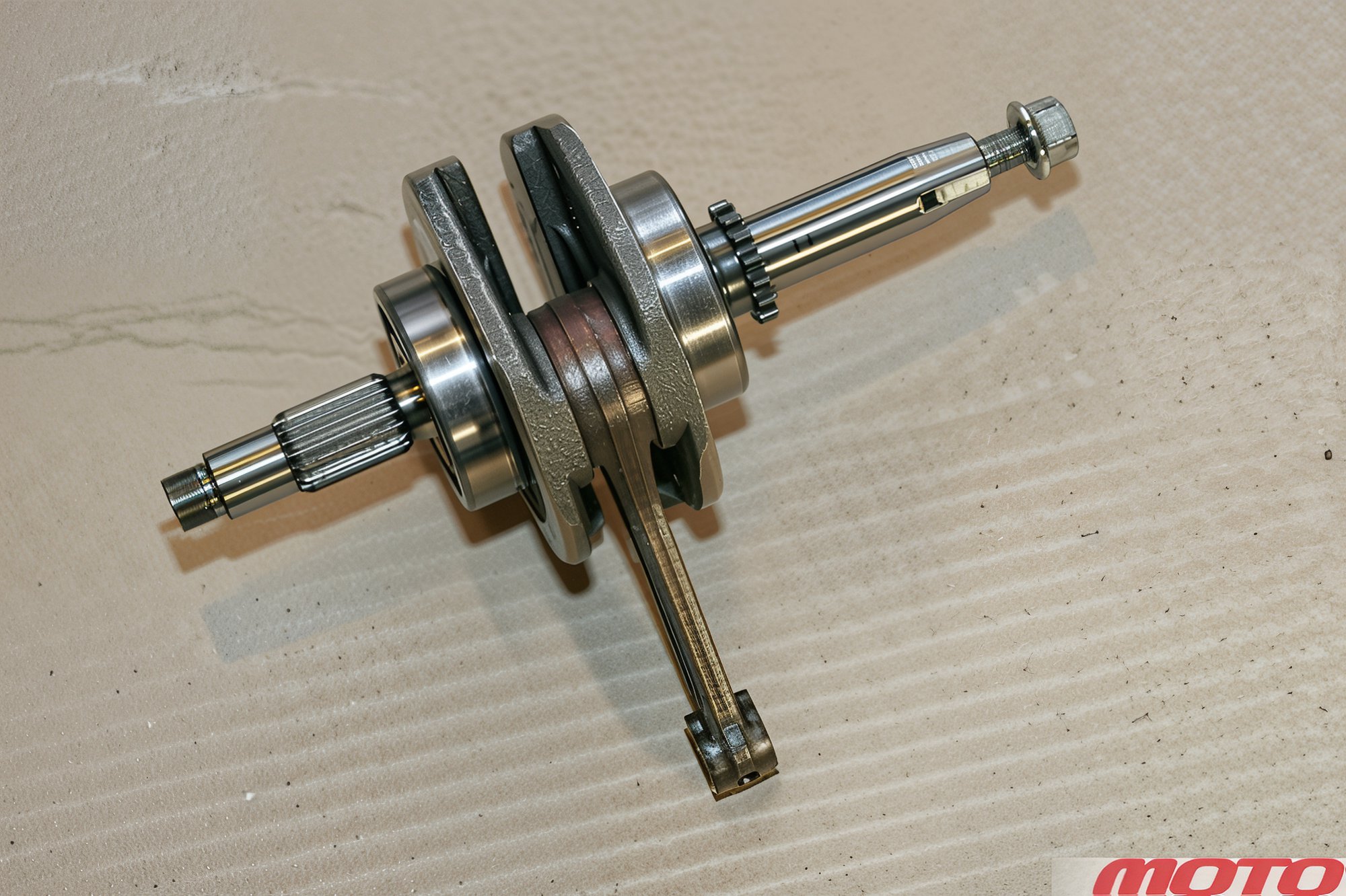
Once the rotor is removed, the crankshaft assembly with bearings can be extracted.
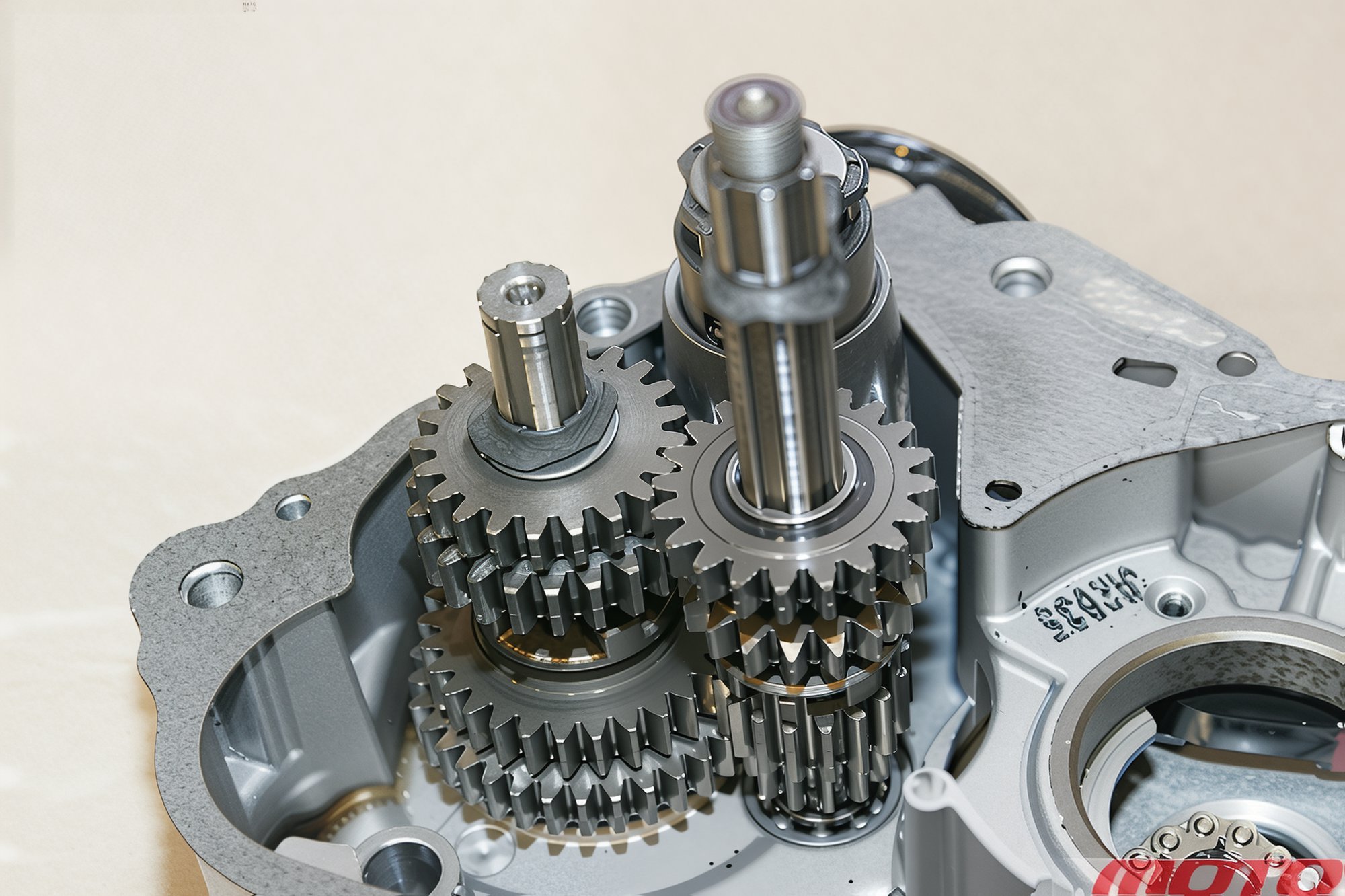
There is no need to remove the transmission shafts unless absolutely necessary, use rubber rings to secure components from falling out.
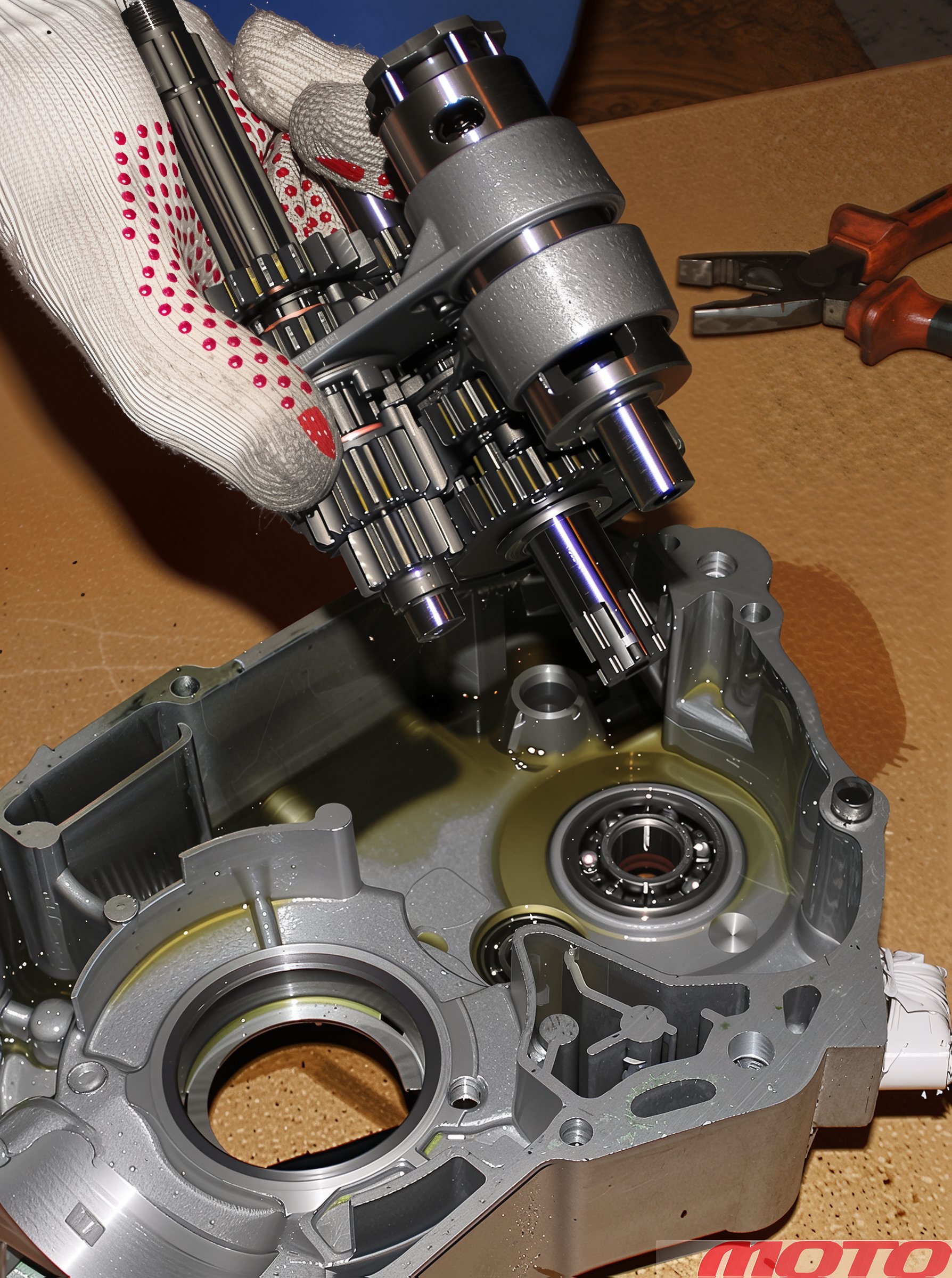
Shafts can be removed as an assembly. To accomplish this...
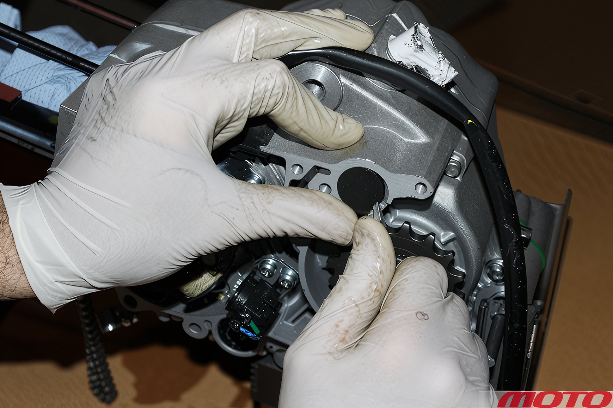
...pry out the locking cap of the copying shaft’s mounting bolt with a screwdriver and extract it...
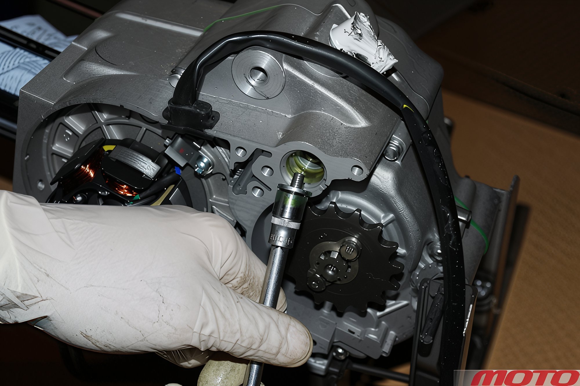
...and unscrew the bolt.
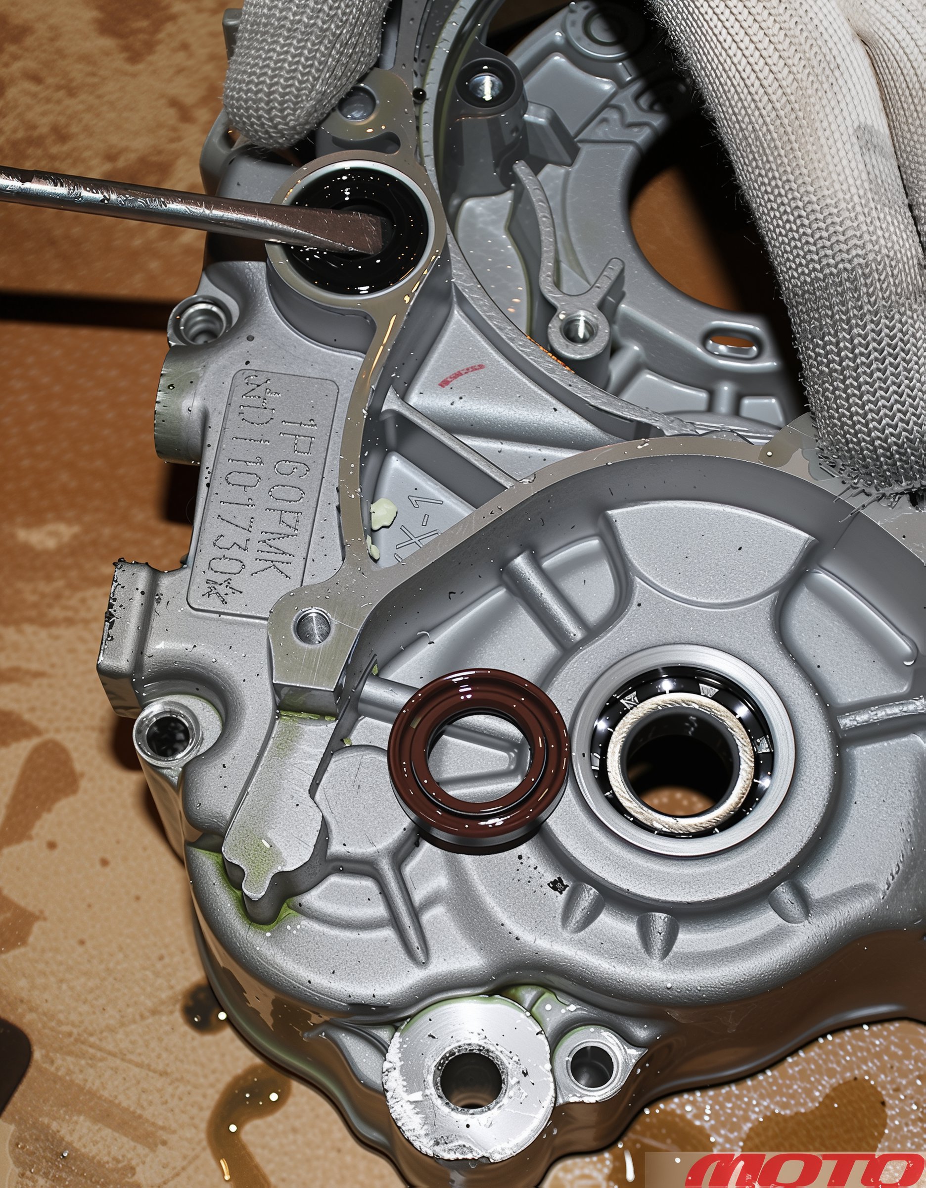
Pry out the seals with a screwdriver...
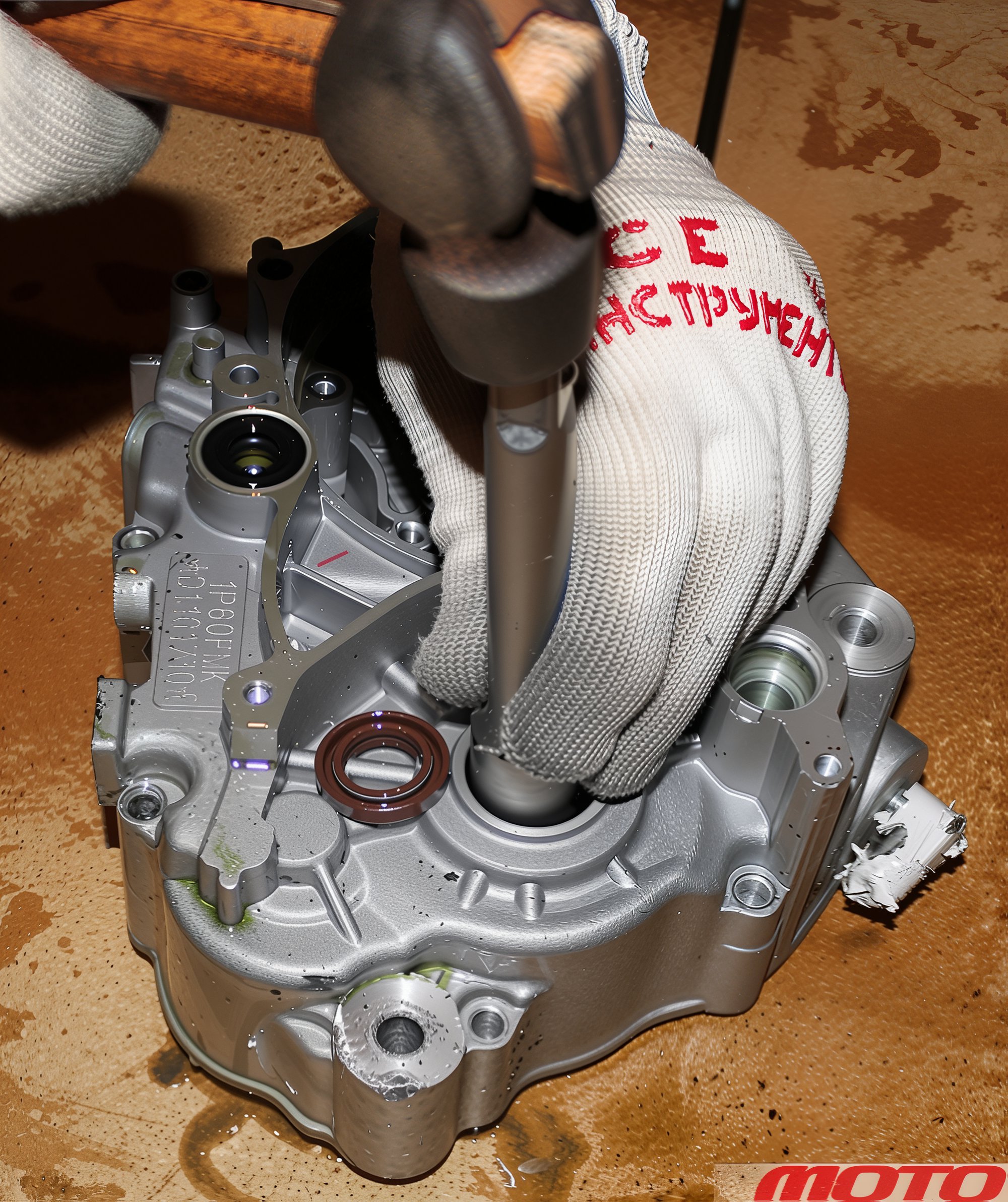
...press the bearings out with a suitable drift.
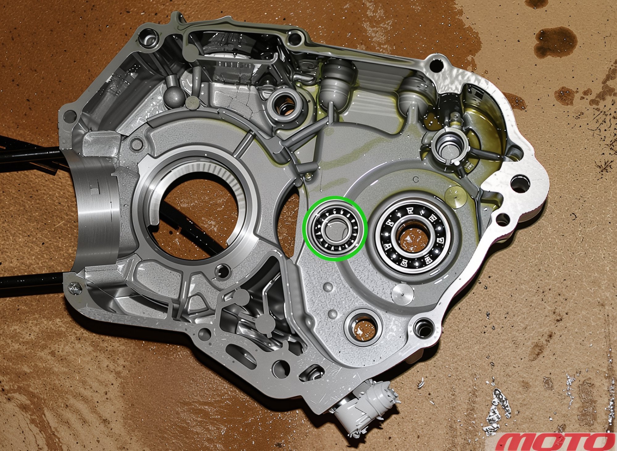
However, to press out this bearing requires a puller. If not, heating the crankcase may be necessary. Reassemble the engine in reverse order. The key is not to rush, and after assembly, ensure all parts have found their correct place. This is why cleanliness and order are half the success.
Cylinder Head Disassembly
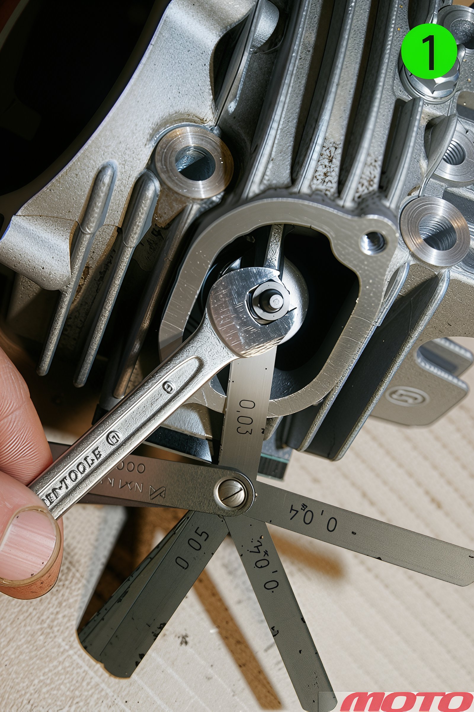
First, measure valve clearances (on cold parts). The ZS150 engine clearances were found to be within 0.03-0.05 mm, although the Scooter-M dealer center we contacted recommends setting them to 0.12-0.15 for both intake and exhaust valves. Typically, the gap doesn't "shift" during disassembly-assembly, so correct adjustment does not necessarily need to be disrupted. However, when replacing or lapping valves and seats, adjustment is mandatory.
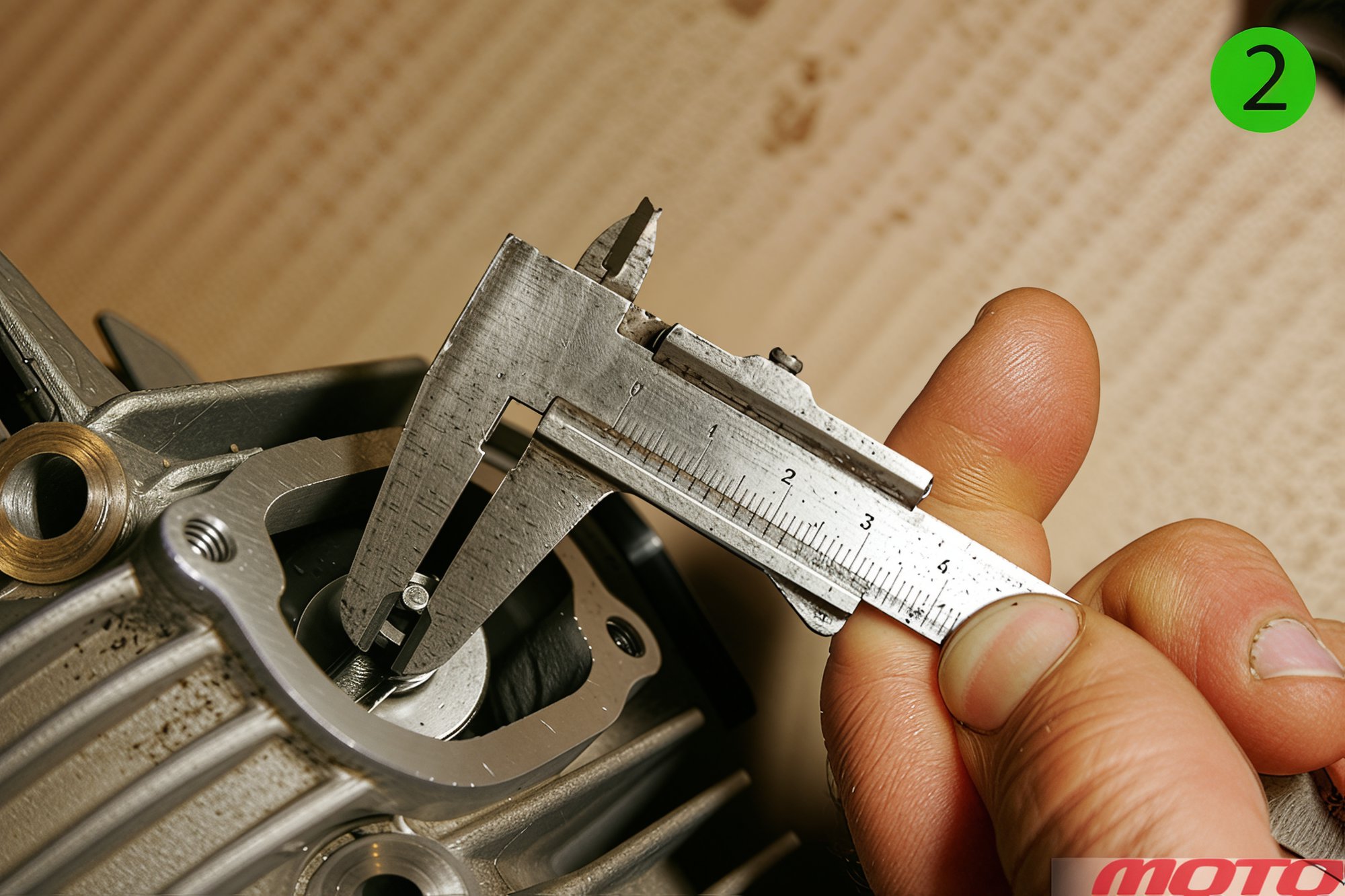
The size for adjustment is 3 mm, although the screw is easily held in place with thin pliers when tightening the nut (9 mm wrench, photo 1).
Use a power screwdriver to unscrew the locking plate screws.
Removing the plate...
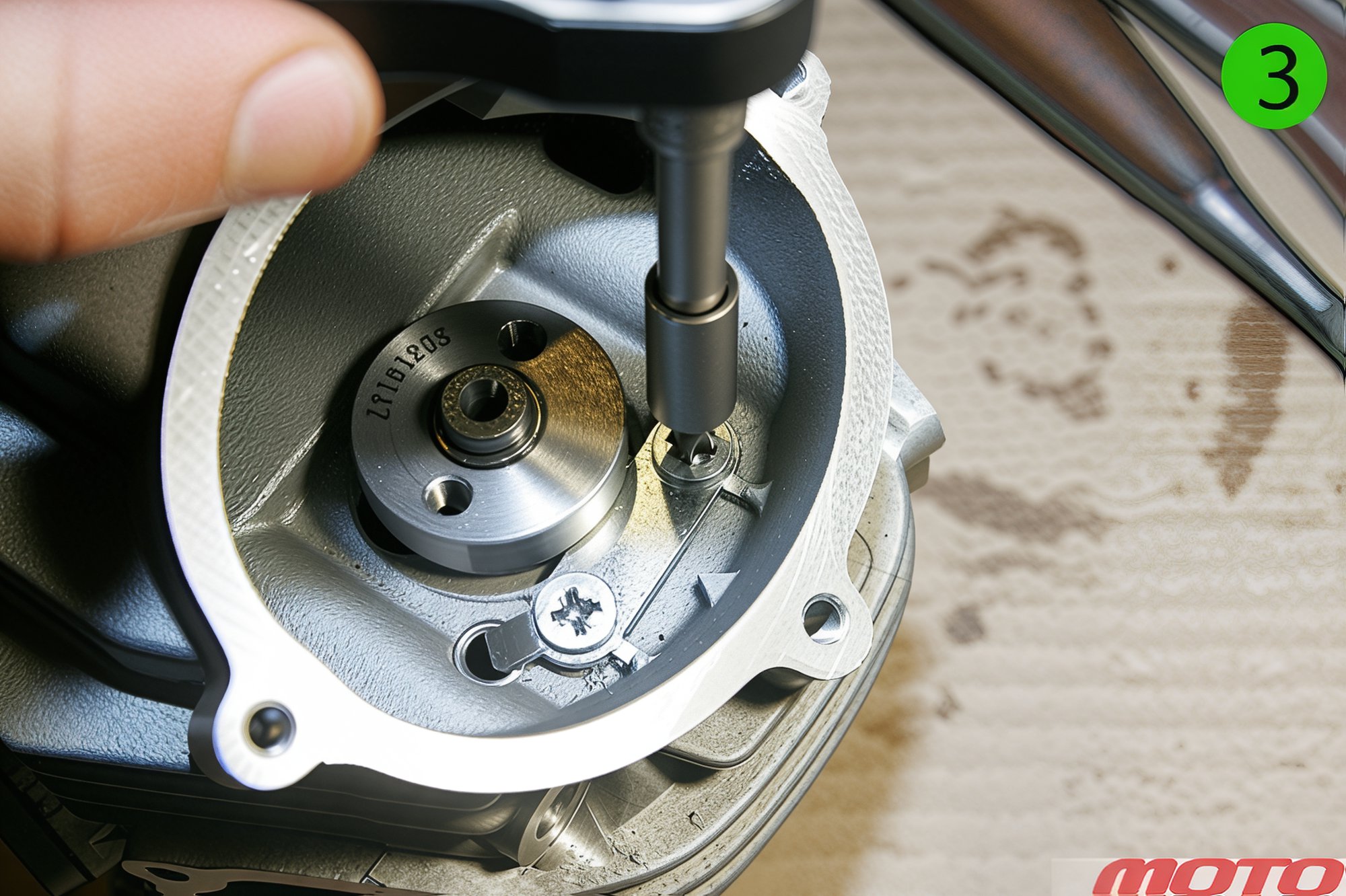
...remove the hollow camshaft pins...
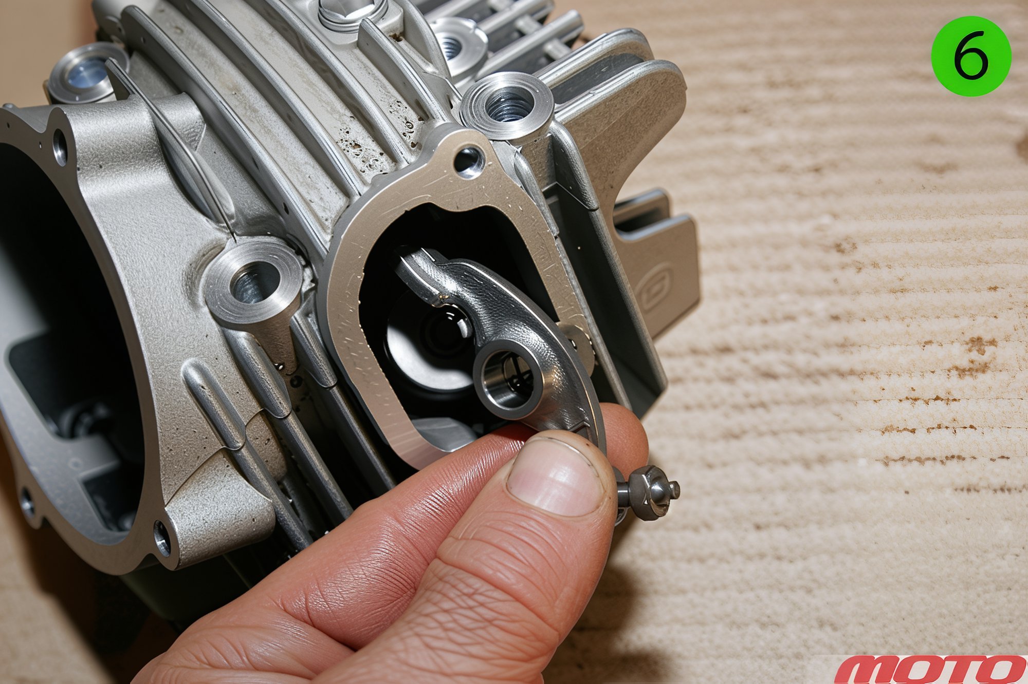
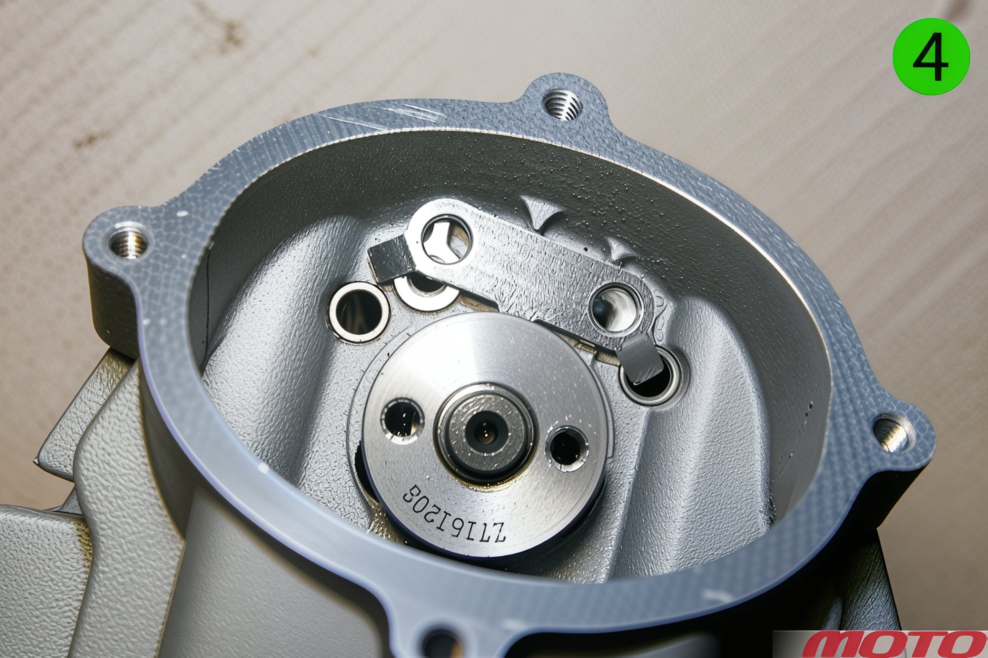
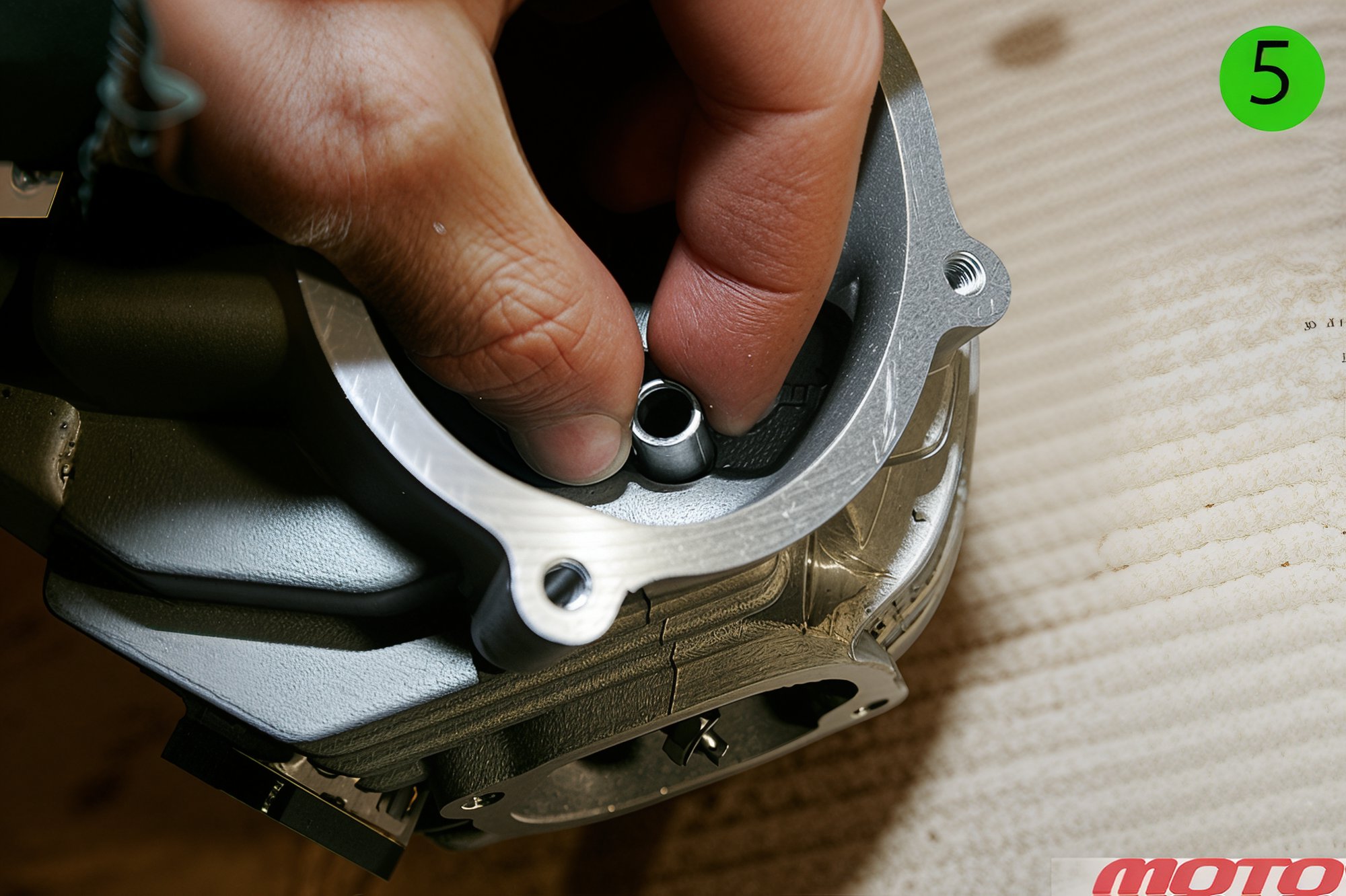
...and the camshafts themselves. Keep the parts organized to maintain adjustments! The camshaft rotates in two bearings tightly seated in the head.
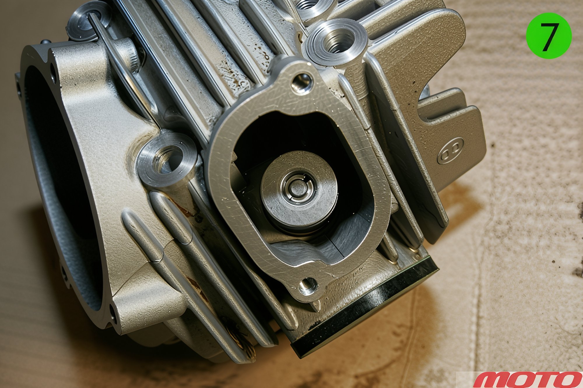
Place a block of wood or soft metal under the cylinder head on the valve side (to support against the valve), press down on the valve spring retainer with a screwdriver or open-end wrench, and use a thin screwdriver (or magnet) to remove the valve keepers.
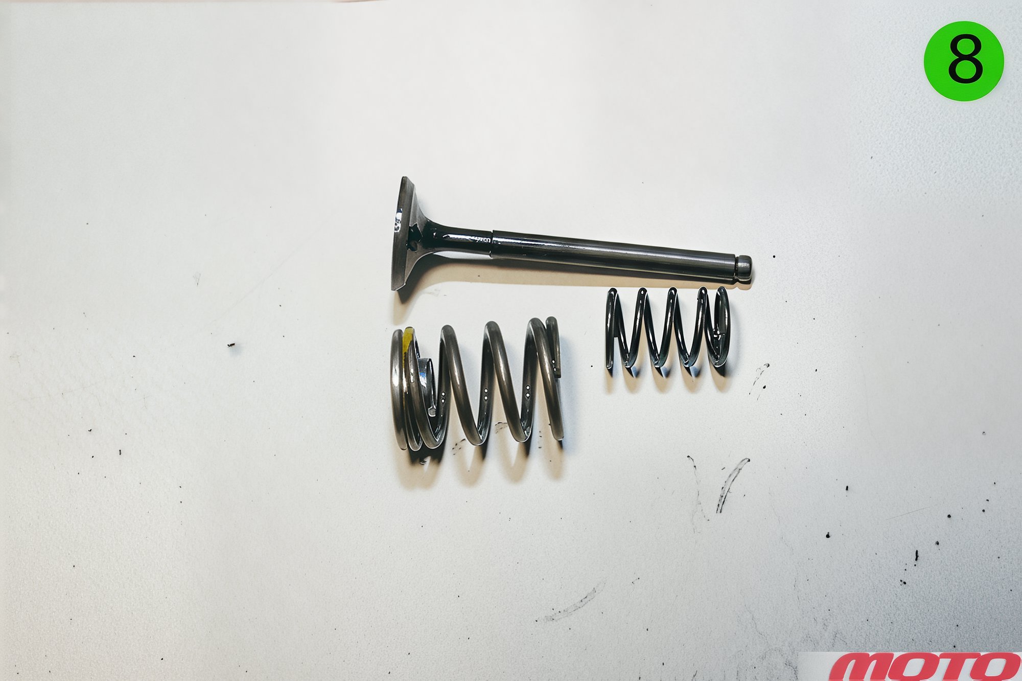
Remove the valve spring retainer, the two springs, and the valve. Note that the valves and springs are different. The intake is larger, and its outer spring on the ZS150 is marked yellow. Be careful during removal and installation not to damage the valve seals (lubricate parts generously with oil during assembly).
Torque Specifications for Key Fastenings:
- Cylinder head nut – 10-12 Nm
- Cylinder head bolt – 9 Nm
- Generator rotor nut – 41 Nm
- Clutch basket nut – 42 Nm
Assembly Reminders:
-
Avoid over-tightening fasteners. A stripped thread in the crankcase can mean the end for the part.
-
Don't lose the guide bushings. They are present on nearly all interfacing surfaces of castings.
-
Remember to bend the locking tabs, peen the flanges, and apply thread-lock (where required).
-
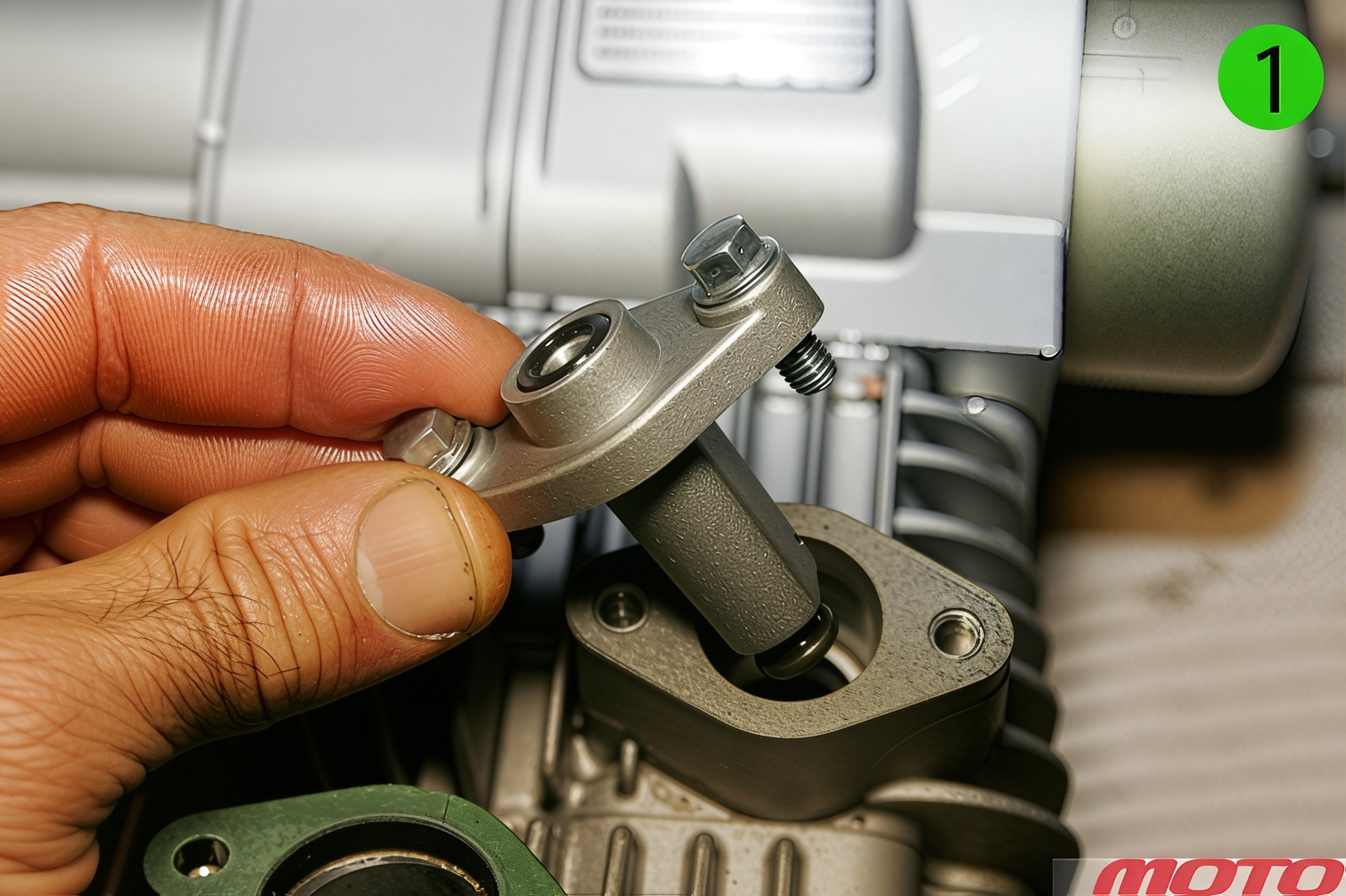
Correctly install the chain tensioner:
-
Begin by removing the central bolt and spring, fully retract the plunger, install and secure the tensioner with bolts...
-
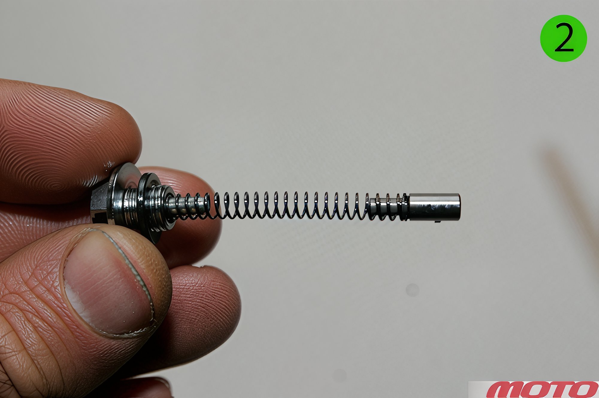
...then insert the spring section (do not lose the small stop at the end!) - you will hear a click - and only after that tighten the central bolt.
-
-
Finally, fill with oil, crank the shaft with the kick, check all timing marks, cycle through the gears, ensure the clutch works, and...you're ready to start it!
Moto Magazine, Issue 01, 2013. Text by Mikhail Kofman and Nikolai Sazonov.